Research Associate at Chemical and Materials Engineering
Professor at Chemical and Materials Engineering
The scale-up/down of an industrial process is still a big challenge.1-3 The mixing conditions should ideally be matched between scales but this is not always feasible.4-7 The difference in vessel sizes can vary from as small as 200 mL in bench scale shake flasks to industrial scale bioreactors with more than 10 000 L.
When biotechnology processes are considered, two constraints may happen:
- Certain levels of energy dissipation must be respected to avoid cell damage, particularly for cells which are grown on microcarrier beads.8,9 As the process usually involves microorganisms that can respond differently under diverse conditions, the procedure for replication of process between different scales is a crucial step of the process design.10-12 A number of authors have shown that many cells are much more sensitive to bubble bursting in surface foams than to direct damage due to mixing conditions at the impeller.13,14
- Efficient dispersion, homogenization and dissolution of additives may be required.
This paper focusses on the requirements for scaling-up or scalingdown processes when an additive needs to be efficiently dispersed and dissolved in a mixing vessel.
Mixing Requirements For Effective Dispersion, Homogenization And Dissolution Of Additives
When a mixing sensitive process is studied at bench scale, several requirements need to be addressed:
- The flow pattern needs be uniform and the formation of inactive zones should be avoided. If regions of inactive flow are formed, the homogenization of the additive will not be efficient.
- To have reliable scale-up data the entire vessel must operate in fully turbulent flow. Transitional flow is not scalable and its occurrence should be avoided.
- Regions of high local concentrations of additive need to be reduced. In other words, the formation of a dispersion plume where the additive is slowly dispersed is to be avoided. If a side reaction that yields an undesired byproduct is present, for example, inefficient dispersion of the chemicals at the point of injection allows for the occurrence of the undesired reaction, which decreases the yield of the desired product/outcome. Efficient dispersion of the additive can be achieved by an increase in the turbulence level at the feed point or by a decrease in the feed flow rate or feed concentration.
- Different levels of turbulence can be required depending on the process objective. If the additive is a solid that needs to be suspended, turbulence is required at the bottom of the vessel; if the additive is a solid that needs to be draw-down from the surface, the process is sensitive to the turbulence at the liquid surface.
- If air entrainment needs to be suppressed, there is a limitation on the maximum turbulence level that can achieved at the liquid surface.
- If there are flocs or other solids that may be damaged by turbulent shear stresses, there is a limitation on the smallest turbulent eddy present in the flow (the Kolmogorov scale). In case of potential damage to these solids, it is usually recommended to keep the Kolmogorov scale significantly larger than the solids, which means decreasing the level of turbulence in the vessel.
Not all these requirements need to be achieved for the same process. The team of process designers need to develop their processes based on the requirements of each application. Extensive information about how to achieve these process objectives can be found at Kresta et al.4 and Cullen et al.5
Several mixing devices are used to develop new processes or replicate industrial conditions at bench scale. The limitations of the two most common devices are described in the next section.
Limitations Of Standard Mixing Devices
The most common mixing devices currently used for bench scale experiments are shaker flasks and stirred vessels.
The development of a biotechnological process is usually started using shaken flasks or even shaken plates at the bench scale, which have a fluid dynamic behavior completely different from an industrial scale bioreactor.15-17 This approach is useful and provides good results for several cases,18,19 especially when the process is not mixing sensitive. As the geometry of a shaker flask and an industrial vessel are different, it is not possible to geometrically reproduce one scale into another. Achieving the same level of energy dissipation of the larger scales may also be problematic.17
Stirred tanks offer the possibility of geometrically similar scale-up. Due to the large impeller diameter at the industrial scale, these vessels easily operate in fully turbulent flow. When operating at standard conditions at bench scale, however, regions of inactive flow that falls into transitional flow frequently occur.20,21 It is usually accepted that a stirred tank is operating in turbulent flow at impeller Reynolds number of 20 000, but it has recently been shown that this assumption is only valid for regions close to the impeller.20 In fact, Reynolds numbers larger than 100 000 are required to sustain fully turbulent flow at the liquid surface, where additives are usually fed.
There are several ways to overcome these problems:
- Addition of a second impeller close to the surface.
- Feed the additive closer to the impeller in the zone of maximum energy dissipation to guarantee fast dispersion, although the insertion of a dip pipe can be challenging in terms of mechanical design.
In recent years, several new mixing devices have been developed to overcome the problems discussed above. The principles of the design of these new vessels are described in the next section.
Development Of New Mixing Devices
There are mixing devices that have been developed recently that intend to provide a more uniform distribution of flow and turbulence and to avoid the presence of dead zones in any part of the vessel. The design of these vessels is based in the following premises: miniaturizing the vessel and confining the flow.4,22-26 These devices tend to be filled with mixing elements (static mixers or impellers), to use confined jets or to operate at the milliliter-scale.
The new geometries bring several advantages. As the flow is confined, the formation of inactive flow zones is significantly reduced. Smaller volumes allow for a better control of the mixing conditions, especially the energy dissipation. They also avoid the occurrence of transitional flow, since some of these vessels can sustain fully turbulent flow at Reynolds numbers as low as 3000.25,26 Among several new mixing geometries (see Chapter 2b in Kresta et al.4), two are described here: the confined impinging jet reactor (CIJR)24,27 and the confined impeller stirred tank (CIST).25
The CIJR, as shown in Figure 1, is a milliliter-scale jet reactor with a very short residence time. This vessel uses two impinging jets that collide and provide a very high energy dissipation in a tight well controlled space. This vessel can provide energy dissipation 1000 times higher than stirred tanks. This tiny vessel is very useful when rapid chemical reactions need to be studied. It may also prove useful to determine the energy required to just break a cell membrane in order to harvest the products of fermentation, or the level of dissipation which can kill a cell when it is applied over a very short time.
 Figure 1. The confined impinging jet reactor (CIJR) is a milliliter scale impinging jet reactor. Typical dimensions are: inlet diameter (d) = 0.25-1.00 mm, outlet diameter (δ) = 0.5-3.0 mm and chamber diameter (D) = 5-19 times larger than the inlet diameter. Figure modifi ed from Johnson and Prud’homme.24
The CIST, as shown in Figure 2, is a fully baffled stirred tank filled with 5-6 impellers. It has several advantages over single impeller stirred tanks.
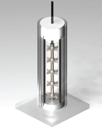 Figure 2.The confined impeller stirred (CIST) is a 7.62 cm diameter and 22.86 cm high stirred vessel filled with 5-6 impellers. This image shows the vessel operating with a set of 5 Rushton turbines and 4 baffles. Each Rushton turbine has a diameter of 3.81 cm.
- It is a 1 L tank, which is one tenth of a standard bench scale stirred tanks (10 L), therefore the volume of broth and the waste are reduced by a factor of 10.
- The region of this vessel where the flow is inactive is less than 3% of the total volume (against 30% of standard singleimpeller stirred tanks operating at Re = 20 000). This vessel can sustain fully turbulent flow in its entire volume at Re = 3 000.
- The decay of the energy dissipation when the fluid is moving away from the impellers is much slower than the decay in standard stirred tanks.
- The submergence (S) is equal to one impeller diameter, which provides enough energy to avoid the formation of a dispersion plume when an additive is fed at the surface.
- The off-bottom clearance is equal to one third of an impeller diameter, which provides enough energy to guarantee active circulation and good solids suspension at the bottom of the tank.
- It can provide a large range of energy dissipations by changing the impeller geometry and rotational speed.
- The high height/diameter ratio of this tank allows an in situ settling test immediately after mixing. No sample transfer is required.
- The small footprint of the vessel allows for several simultaneous experimental runs in the same fume hood.
More details of the dimensions and the geometry of the CIST are provided by Machado and Kresta.25
When using these new mixing devices, scale-up based on direct geometric similarity is not possible. An alternate approach is to keep the mixing energy (J) constant between scales.28 In applying this approach, two conditions have to be met: the vessels in both scales must operate in turbulent flow and the distribution of energy dissipation in the volume of interest must be uniform in both vessels. The mixing energy is given by the product of average energy dissipation (εaverage) in the vessel and mixing time (tmix), as shown in Equation 1:
J= εaverage*tmix (1)
Machado and Kresta28 showed how to apply this principle to a process carried out in an industrial pipeline which is being scaled down to a 1L CIST. Successful results were obtained using this method to replicate bitumen de-watering at the bench scale.29,30
The main advantage of using this procedure is that it allows for the replication of data from different geometries as long the energy dissipation and the mixing time are known. In case of shear sensitive processes, the average energy dissipation can be lowered and the total mixing energy kept constant by increasing mixing time. This procedure is applicable if the mixing energy is the variable that dominates the process; if a different variable (e.g. oxygen transfer rate)31 is dominant, then the scale-up/down method should focus on that variable.
References
- Schmidt FR. Optimization and scale up of industrial fermentation processes. Appl Microbiol Biotechnol. Sep 2005;68(4):425-435.
- Johnson C, Natarajan V, Antoniou C. Verification of energy dissipation rate scalability in pilot and production scale bioreactors using computational fluid dynamics. Biotechnol Prog. May-Jun 2014;30(3):760-764.
- Nienow AW, Nordkvist M, Boulton CA. Scale-down/scale-up studies leading to improved commercial beer fermentation. Biotechnol J. Aug 2011;6(8):911-925.
- Kresta SM, Etchells AW, Dickey D, Atiemo-Obeng VA. Advances in Industrial Mixing: A Companion to the Handbook of Industrial Mixing: Wiley; 2015.
- Cullen PJ, Romañach RJ, Abatzoglou N, Rielly CD. Pharmaceutical Blending and Mixing2015.
- Nienow AW. Hydrodynamics of stirred bioreactors. Appl Mech Rev. 1998;51(1):3-32.
- Reyes C, Pena C, Galindo E. Reproducing shake flasks performance in stirred fermentors: production of alginates by Azotobacter vinelandii. J Biotechnol. Oct 9 2003;105(1-2):189-198.
- Nienow AW, Hewitt CJ, Heathman TRJ, et al. Agitation conditions for the culture and detachment of hMSCs from microcarriers in multiple bioreactor platforms. Biochemical Engineering Journal. 2016;108:24-29.
- Pieralisi I, Rodriguez G, Micheletti M, Paglianti A, Ducci A. Microcarriers’ suspension and flow dynamics in orbitally shaken bioreactors. Chemical Engineering Research and Design. 2016;108:198-209.
- Enfors SO, Jahic M, Rozkov A, et al. Physiological responses to mixing in large scale bioreactors. J Biotechnol. Feb 13 2001;85(2):175-185.
- Rocha-Valadez JA, Galindo E, Serrano-Carreon L. The influence of circulation frequency on fungal morphology: a case study considering Kolmogorov microscale in constant specific energy dissipation rate cultures of Trichoderma harzianum. J Biotechnol. Jul 15 2007;130(4):394-401.
- Mollet M, Ma N, Zhao Y, Brodkey R, Taticek R, Chalmers JJ. Bioprocess equipment: characterization of energy dissipation rate and its potential to damage cells. Biotechnol Prog. Sep-Oct 2004;20(5):1437-1448.
- Nienow AW, McLeod G, Hewitt CJ. Studies supporting the use of mechanical mixing in large scale beer fermentations. Biotechnology Letters. May 2010;32(5):623-633.
- Nienow AW. Mass Transfer and Mixing Across the Scales in Animal Cell Culture. In: Al- Rubeai M, ed. Animal Cell Culture. Vol 9: Springer Interational; 2015:137-167.
- Weheliye W, Yianneskis M, Ducci A. On the fluid dynamics of shaken bioreactors- flow characterization and transition. AIChE Journal. 2013;59(1):334-344.
- Mancilla E, Palacios-Morales CA, Córdova-Aguilar MS, Trujillo-Roldán MA, Ascanio G, Zenit R. A hydrodynamic description of the flow behavior in shaken flasks. Biochemical Engineering Journal. 2015;99:61-66.
- Durauer A, Hobiger S, Walther C, Jungbauer A. Mixing at the Microscale: Power Input in Shaken Microtiter Plates. Biotechnol J. Jul 1 2016;DOI: 10.1002/biot.201600027.
- Büchs J. Introduction to advantages and problems of shaken cultures. Biochemical Engineering Journal. 2001;7(2):91-98.
- Buchs J, Zoels B. Evaluation of maximum to specific power consumption ratio in shaking bioreactors. Journal of Chemical Engineering of Japan. May 2001;34(5):647-653.
- Machado MB, Bittorf KJ, Roussinova VT, Kresta SM. Transition from turbulent to transitional flow in the top half of a stirred tank. Chemical Engineering Science. Jul 19 2013;98:218-230.
- Bittorf KJ, Kresta SM. Active volume of mean circulation for stirred tanks agitated with axial impellers. Chemical Engineering Science. Apr 2000;55(7):1325-1335.
- Betts JI, Baganz F. Miniature bioreactors: current practices and future opportunities. Microb Cell Fact. 2006;5:21.
- Fernandes P, Carvalho F, Marques MP. Miniaturization in biotechnology: speeding up the development of bioprocesses. Recent Pat Biotechnol. Dec 2011;5(3):160-173.
- Johnson BK, Prud’homme RK. Chemical processing and micromixing in confined impinging jets. AIChE Journal. Sep 2003;49(9):2264-2282.
- Machado MB, Kresta SM. The confined impeller stirred tank (CIST): A bench scale testing device for specification of local mixing conditions required in large scale vessels. Chem Eng Res Des. Nov 2013;91(11):2209-2224.
- Hortsch R, Weuster-Botz D. Power consumption and maximum energy dissipation in a milliliter-scale bioreactor. Biotechnology Progress. Mar-Apr 2010;26(2):595-599.
- Fonte CP, Sultan MA, Santos RJ, Dias MM, Lopes JCB. Flow imbalance and Reynolds number impact on mixing in Confined Impinging Jets. Chemical Engineering Journal. 2015;260:316-330.
- Machado MB, Kresta SM. When Mixing Matters: Choose Impellers Based on Process Requirements. Chemical Engineering Progress. 2015;111(7):27-33.
- Laplante P, Machado MB, Bhattacharya S, Ng S, Kresta SM. Demulsifier Performance in Froth Treatment: Untangling the Effects of Mixing, Bulk Concentration and Injection Concentration using a Standardized Mixing Test Cell (CIST). Fuel Processing Technology. October 2015;138:361-367.
- Chong JY, Machado MB, Bhattacharya S, Ng S, Kresta SM. Reduce Overdosing Effects in Chemical Demulsifier Applications by Increasing Mixing Energy and Decreasing Injection Concentration. Energy & Fuels. 2016;30(6):5183-5189.
- Garcia-Ochoa F, Gomez E. Bioreactor scale-up and oxygen transfer rate in microbial processes: an overview. Biotechnol Adv. Mar-Apr 2009;27(2):153-176.