Research Associate at Chemical and Materials Engineering
Professor at Chemical and Materials Engineering
Mixing is a crucial step in many chemical processes. Poor mixing can limit the efficiency of an industrial process or cause severe complications in scale-up. Despite its importance, the replication of mixing conditions at different scales still needs to be better understood. There are several cases where scale-up procedures are known to fail and the reasons are not always clear. When a process is being designed or replicated between scales, as many processing conditions as possible should be held constant, but this is unfortunately impossible for many cases involving reactions or multi-phase flow. When this happens, the rate-limiting variables should be prioritized. Identifying these variables is a decision that needs to be supported by experiments and/or simulations.
The most classical scale-up/-down methodology is geometric similarity where the relative dimensions of a mixing vessel (D/T, C/T…) are kept identical and one of the dynamic properties is chosen to be replicated, usually the power per mass (P/ρV). Even when it is possible to keep geometric similarity between scales and dimensionless groups are also held constant, this approach may not work if:
- The process involves competing rates that depend on local concentration (formation of an undesired product from a mixing sensitive competitive reaction).
- Large scale-up factors are involved. The processing of mineral slurries is a good example. While bench scale tests are run in vessels with a typical diameter of 24 cm, industrial scale vessels may have a diameter larger than 15 m (50 times larger). The particle size distribution rarely scales-down in a straight forward way.
- It is impossible to keep the same geometry for different scales. Biotechnology processes are usually first developed in shake flasks while their industrial version may include an agitated bioreactor with air spargers, different impeller geometries and heat exchangers.
When geometric similarity is not possible, Machado and Kresta1 suggested that the mixing energy is a parameter that may be useful. The mixing energy (J) takes into account the total energy provided to the system and is defined as the product of the energy dissipation and the mixing time (J = ε*tmix). This concept is very useful for the following cases:
- When a process is shear sensitive but a high mixing energy is needed, the energy dissipation (which is an instantaneous value) may be lowered and the mixing energy increased by increasing the mixing time;
- When geometric similarity is not feasible, a similar mixing energy may be scaled between two different vessel geometries.
This approach has been successfully used to replicate industrial conditions at the bench scale for bitumen de-watering processing2 and for liquid draw-down.
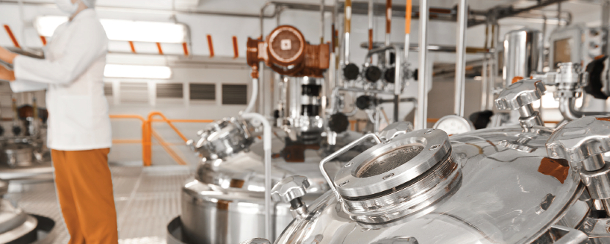
Due to the number of options available, the choice of the bench scale mixing device is a key part of this process. Figure 1 shows several mixing devices that can used for bench scale experiments. The development of chemical processes relied for many years on shake flasks, jar tests, and single-impeller stirred tanks. These vessels are extremely useful and work well for many scenarios, but they also present some problems that cannot be ignored. All of these test geometries present a non-uniform turbulence distribution, regions where the flow is inactive or stagnant and parts of the volume which operate in transitional flow. When any of these problems is present at the bench scale, the process design may be compromised (see Chapter 2B in Kresta, et al.3 ).
 Figure 1. a) Shake flasks (adapted from Kresta, et al.3), b) jar tests (adapted from Kresta, et al.3), c) stirred tank operating with a multi-phase system, d) milliliter-scale bioreactor operating with a one-sided magnetic driven impeller (adapted from Hortsch, et al.33), e) Kar Dynamic Mixer (KDM) showing blending experiments and particle tracks from CFD simulation (adapted from Yu, et al.36), f) NETmix (adapted from Laranjeira, et al.37).
Shake flasks, as shown in Figure 1a, are quite common in applications as diverse as biotechnology, surfactant formulation or replication of ocean waves and are particularly useful when a large number of experiments need to be carried out.4-6 On the other hand, many industrial processes cannot be replicated by these devices.7 Although the distribution of energy dissipation is more uniform than in singleimpeller stirred tanks, the maximum energy dissipation that can be achieved is very low: 0.002 W/kg for unbaffled flasks and 0.1 W/kg for baffled flasks.6 The addition of baffles increases the maximum energy dissipation but also slightly increases the non-uniformity distribution of energy dissipation.8 These devices can also present very long mixing times (over 100 s) which makes the measurement of local concentration effects more difficult.9
Jar tests (Figure 1b) are vessels operating with a single flat-blade impeller and are commonly used for coagulation and flocculation experiments in water treatment.10-12 The flat blade impeller has a large swept volume, but the local energy dissipation rate is 4-6 times higher in the impeller zone than the volume average dissipation rate.13, 14
Stirred tanks are quite well characterized.3 They have a very inhomogeneous energy dissipation distribution, and can also drop from fully turbulent conditions at the mega-scale, where very large Reynolds numbers can easily be reached, to transitional flow over a large part of the vessel on the small scale.15 Even a stirred tank operating in fully developed turbulent flow frequently presents inactive zones (30% of the volume)16 and a non-homogeneous turbulence distribution.17 There are significant differences in the local energy dissipation rate from the impeller region to the bulk, giving εmaximum/εaverage ratios as high as 100. A stirred tank operating with a multi-phase system (oil draw-down into water) is shown in Figure 1c.
In order to overcome the limitations of the shake flasks, jar tests and conventional stirred tanks, several mixing test geometries have been proposed in recent years. The design of these mixing vessels tends to either miniaturize the vessel18-21 and/or confine the flow.22, 23 Both approaches provide a more uniform distribution of turbulence, smaller regions where the flow is inactive or in a transitional flow regime, and better control of mixing.
 Figure 2. a) The confined impinging jet reactor (CIJR) and b) the local energy dissipation rate at a jet Reynolds number of 400 (adapted from Liu and Fox).26
 Figure 3. Decolorization reaction in a confined impeller stirred tank. The tank is filled with a solution of 75wt% of glucose in water and is operating at Re = 150. The images show time
 progressing
from left to right. Due to the low Re, the vessel is not able to sustain turbulent flow and several compartments are formed.Some of the most successful new mixing devices are summarized below. Most of them were developed to operate in fully turbulent flow:
- The confined impinging jet reactor (CIJR),23 as shown in Figure 2a, is a milliliter-scale reactor where two jets impinge generating a region with very high local energy dissipation, up to 1000 times higher than what can be achieved close to an impeller. The CIJR is a continuous device suitable for very intense mixing and short residence times. Figure 2b shows the non-uniformity of turbulence in the vessel. It is used at the bench scale when the process involves fast reactions and is possibly most useful for precipitation reactions. This vessel has been successfully operated with its two impinging jets at flow rates up to 30% different.24 An extensive list of papers describe its characterization23-27 and application.28-31
- Liu, et al.32 designed a multi-inlet vortex mixer (MIVM), which is a four-stream chamber used for flash nanoprecipitation. The equipment allows for well-controlled micromixing conditions at Re > 1 600. This design also allows for different volumetric flow rates. The supersaturation and the final solvent quality can be controlled by varying the stream velocities.
- Hortsch, et al.33presented a milliliter-scale stirred bioreactor (V = 10 mL) which was able to ensure efficient gas-liquid mass transfer in viscous media, distribute power uniformly and prevent wall growth. The vessel has a magnetically driven one-sided paddle impeller with a very high swept impeller volume in an unbaffled tank, as shown in Figure 1d. This vessel was able to sustain fully turbulent flow at Re as low as 4 000.
- Bagheri, et al.34 presented a micro reactor (T = 12.5 mm) with a magnetic stirrer to study the effects of mixing and catalyst choice and showed that mixing plays a role even at the millilitre-scale.
- Machado and Kresta22 characterized a stirred vessel called a confined impeller stirred tank (CIST), which is a 1L tank filled with 5-6 impellers, and showed that this geometry provides a much more uniform turbulence distribution when compared to standard bench scale stirred tanks. The inactive zone is reduced from 30% to less than 5% of the total volume. Figure 3 shows the CIST operating with a solution of 75wt% of glucose in water at a Re = 150. The mixing is observed through a decolorization reaction.35 The CIST was not able to sustain turbulent flow at Re = 150 and several mixing compartments were observed in the vessel. The authors recommend limiting its application to fully turbulent conditions.
- Yu, et al.36 developed the Kar Dynamic Mixer (KDM) impeller to be used on test tubes with high viscosity fluids. This impeller is composed of multiple twisted ribbon elements attached to a rotating shaft. It can be used for fluids with viscosities varying from 5,000 to 30,000 cP. The test tubes had diameters varying from 15 mm to 40 mm and the impeller/vessel diameter ratio was between 0.5 and 0.86. Figure 1e shows the operation of the vessel and also a particle track from CFD simulations.
- Laranjeira, et al.37 described the NETmix, which is a new static mixer that consists of a network of spherical chambers interconnected by cylindrical channels as shown in Figure 1f. This reactor allows for very well controlled mixing conditions because the network structures can be adjusted to ensure the desired yield and selectivity. NETmix has been successfully used to produce nanoparticles with high reproducibility of the size distribution.38
This article describes several new mixing devices that have been developed by the mixing research community. These new devices can overcome the limitations of conventional devices (shake flasks, jar tests and stirred tanks). Research and development professionals now have a range of well characterized mixing test cells to choose from but the best choice still depends on a critical analysis of the process and on the correct assessment of the most critical process mixing constraint.
References
- Machado, M. B.; Kresta, S. M., When Mixing Matters: Choose Impellers Based on Process Requirements. Chemical Engineering Progress 2015, 111, (7), 27-33.
- Chong, J. Y.; Machado, M. B.; Arora, N.; Bhattacharya, S.; Ng, S.; Kresta, S. M., Demulsifier Performance in Diluted Bitumen Dewatering: Effects of Mixing and Demulsifier Dosage. Energy & Fuels 2016, 30, (11), 9962-9974.
- Kresta, S. M.; Etchells, A. W.; Dickey, D.; Atiemo-Obeng, V. A., Advances in Industrial Mixing: A Companion to the Handbook of Industrial Mixing. Wiley: 2015.
- Büchs, J., Introduction to advantages and problems of shaken cultures. Biochemical Engineering Journal 2001, 7, (2), 91-98.
- Mancilla, E.; Palacios-Morales, C. A.; Córdova-Aguilar, M. S.; Trujillo-Roldán, M. A.; Ascanio, G.; Zenit, R., A hydrodynamic description of the flow behavior in shaken flasks. Biochemical Engineering Journal 2015, 99, 61-66.
- Kaku, V. J.; Boufadel, M. C.; Venosa, A. D., Evaluation of mixing energy in laboratory flasks used for dispersant effectiveness testing. Journal of Environmental Engineering-Asce 2006, 132, (1), 93-101.
- Azizan, A.; Büchs, J., Three-dimensional (3D) evaluation of liquid distribution in shake flask using an optical fluorescence technique. Journal of Biological Engineering 2017, 11, (1).
- Peter, C. P.; Suzuki, Y.; Rachinskiy, K.; Lotter, S.; Buchs, J., Volumetric power consumption in baffled shake flasks. Chemical Engineering Science 2006, 61, (11), 3771-3779
- Rodriguez, G.; Anderlei, T.; Micheletti, M.; Yianneskis, M.; Ducci, A., On the measurement and scaling of mixing time in orbitally shaken bioreactors. Biochemical Engineering Journal 2014, 82, 10-21.
- Yu, W. Z.; Gregory, J.; Campos, L.; Li, G. B., The role of mixing conditions on floc growth, breakage and re-growth. Chemical Engineering Journal 2011, 171, (2), 425-430.
- Kan, C. C.; Huang, C. P.; Pan, J. R. S., Time requirement for rapid-mixing in coagulation. Colloids and Surfaces A-Physicochemical and Engineering Aspects 2002, 203, (1-3), 1-9.
- Rossini, M.; Garrido, J. G.; Galluzzo, M., Optimization of the coagulation–flocculation treatment: influence of rapid mix parameters. Water Research 1999, 33, (8), 1817-1826.
- Cheng, C.-Y.; Atkinson, J. F.; Bursik, M. I., Direct Measurement of Turbulence Structures in Mixing Jar Using PIV. Journal of Environmental Engineering 1997, 123, (2), 115-125.
- Stanley, S. J.; Smith, D. W., Measurement of Turbulent-Flow in Standard Jar Test Apparatus. Journal of Environmental Engineering-Asce 1995, 121, (12), 902-910.
- Machado, M. B.; Bittorf, K. J.; Roussinova, V. T.; Kresta, S. M., Transition from turbulent to transitional flow in the top half of a stirred tank. Chemical Engineering Science 2013, 98, 218- 230.
- Bittorf, K. J.; Kresta, S. M., Active volume of mean circulation for stirred tanks agitated with axial impellers. Chemical Engineering Science 2000, 55, (7), 1325-1335.
- Zhou, G. W.; Kresta, S. M., Impact of tank geometry on the maximum turbulence energy dissipation rate for impellers. AIChE Journal 1996, 42, (9), 2476-2490.
- Brivio, M.; Verboom, W.; Reinhoudt, D. N., Miniaturized continuous flow reaction vessels: influence on chemical reactions. Lab Chip 2006, 6, (3), 329-44.
- Fernandes, P.; Cabral, J. M. S., Microlitre/millilitre shaken bioreactors in fermentative and biotransformation processes – a review. Biocatalysis and Biotransformation 2006, 24, (4), 237-252.
- Kumar, S.; Wittmann, C.; Heinzle, E., Minibioreactors. Biotechnology Letters 2004, 26, (1), 1-10.
- Lattermann, C.; Buchs, J., Microscale and miniscale fermentation and screening. Curr Opin Biotechnol 2015, 35, 1-6.
- Machado, M. B.; Kresta, S. M., The confined impeller stirred tank (CIST): A bench scale testing device for specification of local mixing conditions required in large scale vessels. Chemical Engineering Research & Design 2013, 91, (11), 2209-2224.
- Johnson, B. K.; Prud’homme, R. K., Chemical processing and micromixing in confined impinging jets. AIChE Journal 2003, 49, (9), 2264-2282.
- Siddiqui, S. W.; Zhao, Y. A.; Kukukova, A.; Kresta, S. M., Characteristics of a Confined Impinging Jet Reactor: Energy Dissipation, Homogeneous and Heterogeneous Reaction Products, and Effect of Unequal Flow. Industrial & Engineering Chemistry Research 2009, 48, (17), 7945-7958.
- Fonte, C. P.; Sultan, M. A.; Santos, R. J.; Dias, M. M.; Lopes, J. C. B., Flow imbalance and Reynolds number impact on mixing in Confined Impinging Jets. Chemical Engineering Journal 2015, 260, 316-330.
- Liu, Y.; Fox, R. O., CFD predictions for chemical processing in a confined impinging-jets reactor. AIChE Journal 2006, 52, (2), 731-744.
- Li, W.-F.; Du, K.-J.; Yu, G.-S.; Liu, H.-F.; Wang, F.-C., Experimental study of flow regimes in three-dimensional confined impinging jets reactor. AIChE Journal 2014, 60, (8), 3033- 3045.
- Gavi, E.; Marchisio, D. L.; Barresi, A. A., On the Importance of Mixing for the Production of Nanoparticles. Journal of Dispersion Science and Technology 2008, 29, (4), 548-554.
- Chiou, H.; Chan, H.-K.; Heng, D.; Prud’homme, R. K.; Raper, J. A., A novel production method for inhalable cyclosporine A powders by confined liquid impinging jet precipitation. Journal of Aerosol Science 2008, 39, (6), 500-509.
- Ma, C. Y.; Liu, J. J.; Zhang, Y.; Wang, X. Z., Simulation for scale-up of a confined jet mixer for continuous hydrothermal flow synthesis of nanomaterials. The Journal of Supercritical Fluids 2015, 98, 211-221.
- Siddiqui, S. W.; Unwin, P. J.; Xu, Z. H.; Kresta, S. M., The effect of stabilizer addition and sonication on nanoparticle agglomeration in a confined impinging jet reactor. Colloids and Surfaces a-Physicochemical and Engineering Aspects 2009, 350, (1-3), 38-50.
- Liu, Y.; Cheng, C.; Prud’homme, R. K.; Fox, R. O., Mixing in a multi-inlet vortex mixer (MIVM) for flash nano-precipitation. Chemical Engineering Science 2008, 63, (11), 2829-2842.
- Hortsch, R.; Stratmann, A.; Weuster-Botz, D., New milliliter-scale stirred tank bioreactors for the cultivation of mycelium forming microorganisms. Biotechnology and Bioengineering 2010, 106, (3), 443-51.
- Bagheri, S. R.; Gray, M. R.; Shaw, J. M.; McCaffrey, W. C., In Situ Observation of Mesophase Formation and Coalescence in Catalytic Hydroconversion of Vacuum Residue Using a Stirred Hot-Stage Reactor. Energy & Fuels 2012, 26, (6), 3167-3178.
- Cabaret, F.; Bonnot, S.; Fradette, L.; Tanguy, P. A., Mixing Time Analysis Using Colorimetric Methods and Image Processing. Ind. Eng. Chem. Res. 2007, 46, 5032-5042.
- Yu, Z.; Cope, R. F.; Kar, K. K.; Even, R. C.; Guillaudeu, S. J., Mixing Performance of the Novel Kar Dynamic Mixer Impeller in Small Laboratory-Scale Systems. Industrial & Engineering Chemistry Research 2012, 51, (46), 15282-15292.
- Laranjeira, P. E.; Martins, A. A.; Nunes, M. I.; Lopes, J. C. B.; Dias, M. M., NETmix®, a new type of static mixer: Experimental characterization and model validation. AIChE Journal 2011, 57, (4), 1020-1032.
- Silva, V. M. T. M.; Quadros, P. A.; Laranjeira, P. E. M. S. C.; Dias, M. M.; Lopes, J. C. B., A Novel Continuous Industrial Process for Producing Hydroxyapatite Nanoparticles. Journal of Dispersion Science and Technology 2008, 29, (4), 542-547.
Editor's Note: All images are copyright of their original publishers.