Abstract
The continuous manufacturing of pharmaceutical compounds and fine chemicals is in high interest for the industry due to significant technical, quality, and economical advantages. Beside the more efficient, safer, and greener synthesis route, a new process design paradigm and equipment selection and design is required. Mechanistic modeling and simulation tools are being used for equipment sizing, equipment chracterization, process design, process integration via steady state modeling, and technoeconomic analysis. Defining system dynamics to correlate critical quality attribute of final product to critical process parameters is crucial for ensuring consistent product quality and process robustness. This work will provide a high-level overall view on applications of modeling and simulation tools for the process and equipment design considerations.
Introduction
Continuous pharmaceutical manufacturing (CM) applications have been demonstrated in bioprocessing and small-molecule drug facilities at different scales and fashions. Some of the major benefits of CM include faster speed to market, better process control, smaller factory/ equipment and environmental footprints, more consistent product quality, modular manufacturing, and lower capital and operating costs.1,2 Although the product design, chemistry, biology, drug delivery method, and efficacy of the drugs are defined by chemists, biologists, and medical experts, equipment and process design are the domain of chemical engineers and process designers. The fundamental knowledge and skill sets for equipment design and sizing, process design and integration, process control, and manufacturing methodologies are key engines behind creating a robust process to deliver consistent quality and an economically viable yield. One of the tools in our process design arsenal is utilization of computational models and process simulations, especially mechanistic modeling tools. A mechanistic model is a knowledge-based description of a system designed to help an observer understand how the system works and predict its behavior. A mechanistic model (based on first-principle knowledge) is a predictive tool that through proper development, validation, and implementation enables applicants to reduce cost, time, and resources for scale-up and technology transfer. It helps by significantly reducing the DoE effort and by finding optimal conditions for equipment sizing and process parameters.
Subscribe to our e-Newsletters
Stay up to date with the latest news, articles, and events. Plus, get special offers
from American Pharmaceutical Review – all delivered right to your inbox! Sign up now!
Each CM process design could be varied to address a specific application, as the technoeconomic criteria, products, steps, and scales vary between applications. CM processes can be fully end- to-end continuous, a hybrid of batch and continuous, or individual continuous operations retrofitted in a batch process (mostly for legacy processes). Selection of the approach is guided by an evaluation of the product, process, equipment, regulations, enterprise readiness, technology availability, market demand, and volume and/or value of the product. Teoh et al.3 proposed a decision-making methodology to evaluate converting pharmaceutical processes from batch to continuous or hybrid.4 It consists of three stages: initial screening, extended evaluation, and process execution (Figure 1).

Pharmaceutical manufacturing is a broad industry in which CM can be applied to different domains. Figure 2 indicates relevant CM methods that can be applied to discrete domains, but domain can be connected in an end-to-end fashion to create a fully continuous process. For instance, synthesis and purification (drug substance), formulation and blending (drug product), and tablet production can all be combined in one train.
The main benefits of CM of APIs can be summarized in four main categories:
- Process intensification for reduced footprint and energy/ resources utilization to reduce manufacturing cost (Capex versus Opex).
- Higher throughput over long production time and improving logistics planning
- More consistent product quality and easier automated control
- Enabling platform for new synthesis routes and green chemistry and safety
The process scale-up is more attainable in comparison to batch, and the modularity nature of the process equipment can bring significant flexibility in process changes and time for execution and new process/location development. The smaller footprint requires less GMP utility and cost and smaller skids, which don’t need extensive foundation preparation and buildings.5 Moreover, reactions involving hazardous gases or explosive intermediates, when run in large volume and cumulated amounts, pose a safety issue. In CM, due to the smaller dimensions and small cumulation, the process becomes safer and greener.6
The main challenges for the paradigm shift from batch to continuous processes can be categorized into four categories:
- Asset utilization (in compare to the existing batch equipment) and new investment justification
- Cultural issues in organization, training for operators, and entrenchment of batch operation practice
- Regulatory concerns for change of process
- Demand and logistic for short-term needs and “small batch” purchases
The pharmaceutical industry has traditionally preferred batch processing largely because of GMP documentation and traceability purposes and asset utilization; although the chemical engineering knowledge of CM process and equipment has increased recently. For many API manufacturers the expensive batch scale equipment is paid off over years and the ROI analysis for new Capex doesn’t make sense. This reinvestment burden extends to regulatory certificates, customer approved processes training operators, operation cost, and a lack of process rejuvenation appetite convince them to keep the status quo, especially when the profit margin is large enough that it covers inefficiencies in the manufacturing process.
It was mentioned before that the CM can be a hybrid mode of some batch steps and some continuous or end-to-end continuous. The process starts with incoming raw material from supply chain (or being produced on site), synthesis of crude API, and purification and final form preparation (Figure 3). Due to GMP requirement or process needs, there are several types of information need to be generated, monitored, and recorded. Figure 3 provides an overview of the API process work flow along with analytical needs and typical equipment used to meet those needs. PAT tools, control systems (SCADA), some surge vessels, and deviation valves also will be used along the process. The CM components work in tandem in a harmonized fashion (material flow and data flow) without interruption. The telescopic and connectivity of the process creates two major differentiating concepts with batch as detailed here:

- Residence Time Distribution (RTD): This is an important measure for any disturbance in the system, control strategy, and start-up and steady state operation. Although the material flow could pass process/material disturbances, the rate and pattern are not an ideal plug flow curve, especially for the CSTRs in the system. The overall RTD also is separated to individual equipment RTD and process RTD. There is also a possibility to define interim RTD, for instance, for synthesis section (including several reactors and separators). The RTD shows how the system responds to any duration and magnitude of material/ process disturbance. For example, if one of the reagents pump trips for 10 seconds and flowrate of that reagent ramps down to 80% (disturbance of 20% for 10 seconds) then: A) what would be the effect on distribution of impurity over time (or other unreacted reagent), B) how long would it take to notice the effect in downstream, and C) how long would it take to regain the steady condition after the disturbance resolves (by operator intervention, or control system).
- Upstream effect: As described above, the process connectivity required continuous flow of material from the start of the process to the downstream steps. Any changes in upstream, in inlet material, or at process parameters, would change the entering materials to the consecutive steps. The changes can be in flowrate of materials, for example for the pump failure case, or product/by-product ratio, for example due to temperature change in reactor (heater/cooler failure). The utilization of surge drums and deviation valves become very important here to interrupt the flow and maintain the quality and flow of materials trickling to the downstream steps. The surge drums and deviation valves location and decision on volume and activation mode comes from process modelling or experimental evaluation and will be defined in the design stage. Some mitigation plans also could be necessary to protect equipment. For instance, if a process disruption could cause solid formation in the line and the solid content could precipitate and blocks the transfer line, then solvent injection will be required to flush the line before the process collapses.
For many of the mentioned CM processes a new synthesis route has been developed, by new solvents, process conditions, reduced steps, new catalysts, new equipment, or new activation methods such as photochemistry. Although the reactions are designed to be efficient with high selectivity, some new impurities could be formed from side reactions that are being studied in the new impurity fate map. Also new risk assessments to identify the Critical Quality Attributes (CQA), Critical Process Parameters (CPP), and Critical Material Attribute (CMA) effects have been performed. The CQAs for final API are similar to the batch process, mostly on impurity level, particle size distribution, polymorph content and stability. The key objective for the new flow-chemistry process is to produce the same APIs at a lower overall cost, with a safer and more efficient process that is easier to run and control, in a shorter amount of time, with fewer steps, in a greener fashion, and with consistent quality.
Process Development Workflow for Continuous Manufacturing
The fundamentals of continuous processes, such as residence time and RTD, dispersion, heat and mass transfer rates, mixing time, Damköhler number, and so on are taught in core chemical engineering courses.8 When considering CM for a pharmaceutical application, the complexity of the processes and products, required quality consistency, and regulatory criteria add additional challenges. These complexities necessitate teamwork and collaboration between chemists, engineers (process, mechanical, automation), management, and regulatory teams. The diversity of constraints, requirements, organizational cultures, and technical languages can make CM process development a challenge.
Mechanistic models can be divided into two types based on their objectives, and can be used for brownfield or greenfield projects for a CM process:
- When the inputs to the process are known and the output variables are to be determined, the problem is called a rating simulation. For instance, for a given equipment size and process condition, such as temperature (existing equipment), the goal of the simulation could be determining the distillation performance for solvent recovery. This approach is common in retrofitting existing equipment for a new process, technology transfer between sites, and improving asset utilization.
- On the other hand, if the outputs of the system are the desired values, and the model must determine the input variables to fulfill the desired output, the problem is called a design problem. The solution methodology consists of treating the problem as an optimization problem. This case is the most common case for API CQAs where the target quality or yield is set and the CPPs or process set-up was optimised to fulfill the requirements.
Figure 4 summarizes the information required to execute this workflow for a small molecule drug substance. The workflow begins by collecting the information about the molecule and synthesis route. This includes the main product, side products, reagents, and catalysts, as well as required reaction, purification, and crystallization steps. The medicinal chemistry team will provide most of the information for chemical engineers at this stage.

For most common pharmaceutical compounds, the chemistry is a multistep process of gradually making intermediates and possibly isolating certain intermediates between stages. The reactions can be multiphase and/or homogeneous and at different temperatures or pressures. Small-scale lab experiments at different residence times, temperatures, and concentrations produce estimates of kinetic parameters. Similarly, for purification, vapor-liquid-liquid equilibrium (VLLE) data is required for distillation, or nucleation/crystallization kinetics for crystallization. In addition, heat-transfer rates, RTD, side reaction rates and mechanisms, yield, controllability, safety, and other classic chemical engineering design considerations are all required for process development.8
Most of the processes, e.g., heat transfer, mass transfer, crystal growth, mixing, etc., are scale-dependent. The scale-up study - from small lab scale to pilot and manufacturing - requires its own effort, and typically involves modeling and simulation.9 Although CM uses volumes much smaller than batch processes, even scaling up from microfluidics to a 10-mm inner diameter PFR is significant and requires a thorough study.10
Batch processes are dynamic, with variables such as concentrations, reaction rates, and adsorption rates constantly changing over time during a batch. The continuous processes are in a steady-state mode, so the variables and parameters remain constant and do not change with time. The differential equations thus obtained do not have any temporal derivative. The model equations are simple since time is not present in these equations. However, the steady-state simulations are not capable of predicting the dynamic behavior of the process. Start- up and shutdown of a unit operating continuously also constitute dynamic processes.
Mechanistic models enable a powerful tool called virtual multidimensional DoE to be used, by which hundreds of DoE cases (for equipment design and process conditions) can be virtually run by global sensitivity analysis. The experimental DoE designs are limited to a few affordable or possible cases because of time and resource constraints. Therefore, the results might not be wholistic or not capable of defining globally optimal conditions. Virtual multidimensional DoE is a strong and low-cost tool for optimal equipment sizing and finding the best process parameters to reach CQA at high profitability. Also, by performing what-if analysis, it can be used for risk analysis and process control strategy development.
Crystallization is a challenging step for process development and scale-up. Many factors can cause lab-scale (e.g., 50 mL) product quality or equipment performance to deviate at larger scales (e.g., 10 L). Nucleation and crystal growth (and breakage/agglomeration or polymorph change) at a larger scale depend on mixing and heat and mass transfer. Cooling crystallization processes are prone to encrustation at the heat transfer surface. In contrast to MSMPRs, plug- flow crystallizers are capable of sequential multizonal heating/cooling to dissolve encrusts and to tune particle size.11
Continuous anti-solvent and reactive crystallizations are more sensitive to mixing. For cases where the mixing underperforms, a low ratio of mixing to reaction/crystallization can push the PSD to an undesired range. However, the mixing performance is not easy to predict and control by simply increasing the speed. The high tip speed of the impeller could increase particle-particle, particle-wall, or particle- impeller interactions that could cause breakage, agglomeration, or generation of new fine seeds and heterogeneous nucleation.11 To avoid this issue, process designers perform Computational Fluid Dynamics (CFD) parametric case studies with a variety of different impeller types, baffles (sizes, number, and location), and vessel designs and geometries.12,13
Process Integration and Steady-State Simulation
After individual equipment has been sized and characterized for the continuous process, engineers should perform flowsheet modeling at a steady-state to map the process. At this stage, models can be used to perform sensitivity analyses, define deviation valves placement, size surge vessels, balance the upstream and downstream flow, etc. Conventional simulation platforms are useful tools for this purpose (Figure 5).

The equipment sizing and telescopic process design should be performed in a synchronized fashion. In hybrid processes the design flexibility is higher. The steady state simulations can be used for evaluating the process performance at different scale and set-ups, reduce inefficiencies, and improve the process flow. For such telescopic systems, the individual equipment sizing, then entire process train will be modelled for design space characterization and defining CPPs. Further evaluation of the process performance by models, and validating by some experiments, can be used for process optimization and scaling up, number up, or scaling out.6
Feeding Systems
The input materials and precursors can be solid, gas and liquid. Conventional pumps and gas cylinders and manifolds could provide the reliable supply of feed for long time. However, solids would need to dissolve in a solvent prior to feeding. In most cases, two dissolution tanks will be used, one is charging with solvent and solids and stirring for a required time to reach homogeneity, and one at service. Inline filters will be used to ensure capturing any undissolved particle entering the system.14
Heating or Cooling
The material can be heated or quenched in an individual step or in the reactor. The intensified process provides robust control on temperature. Heat sources can be by radiation (microwave, laser, light) or heat exchanger by a medium.
Reactors
The reactors come in different designs, shapes, geometry, and materials, but conventionally are PFR or CSTR. The “larger” size PFRs and CSTRs require a mixing tool. The microreactors with 2-5 mm ID normally do not required internal static mixers. Although the flowrates are normally very low (low Reynolds number), the small tube diameter creates a fast radial diffusion and low radial dispersion. Smaller dimensions of the reactor result in a well-defined laminar flow regime. Typical for that is the parabolic flow profile with a broad residence time distribution. The dispersion is mostly axial, however, in most of the coiled tubes the Dean’s flow effect enhance the radial mixing.15 For larger tubes (more than 7mm ID), and especially with multiphase systems, internal segmented mixers, or other mixing tools will be used. CSTRs are less common in flow-chemistry, but some processes use cascade CSTRs and also for combined steps, such as reactive crystallization. Single CSTRs have broad residence time distributions and low conversion rates per unit volume. For a detailed discussion on choosing between CSTRs, PFRs, and microreactors and characteristics refer Reference 6. Computational Fluid Dynamic (CFD) simulation for multiphase flow and multiphysics phenomena is a very helpful tool for scaling up and design optimization in a fast and efficient way. The CFD can be used for optimizing the geometry and design of a vessel (reactor, crystallizer, dryer, etc.), optimizing process parameters (e.g. rpm of mixer or addition rate of reagents), and equipment characterization. Then utilizing a large parametric study via CFD simulation can provide a holistic view on the design space to find global optimum conditions to meet process criteria (such as yield) or product criteria (such as impurity level from side reactions, or particle size distribution of crystals). Figure 6 shows CFD simulation of a mixing regime in a CSTR reactor.

Separation and Work-Up
Continuous filtration (membrane or LLE), distillation, chromatography columns (simulated moving bed), and continuous crystallization are well-developed for different applications and available at various scales. The continuous crystallization is one of the most critical steps of the process, since most of the CQAs can be altered here. Impurity entrapping in the crystals, or change of particle size distribution, polymorph change, solvate channel formation, encrustation and process stability issues all make this step challenging and critical. Two main types of the continuous crystallizers are Mixed Suspension Mixed Product Removal (MSMPR) and Oscillatory Baffled Crystallizers (OBC). Interested readers can refer to the Handbook of Continuous Crystallization for further details.11
Steady-state models can also allow engineers to conduct a risk analysis and failure mode study. For instance, if some of the reactions produce insoluble intermediates or products with a tendency to precipitate out of the reaction, this could cause clogging of the pipes and equipment. In this case, the design engineer has two options:
- Change the process/equipment (e.g., use a CSTR instead of a PFR) or divide the challenging step into two steps to quench and restabilize the solution with additional solvent or at a different temperature
- Add a significant amount of excess solvent to the step (and up scale the equipment to the corresponding new volumetric flow-rate) to solubilize the compound.
For the latter, more common option, the effect of increasing the size of the equipment and impacts to downstream equipment need to be further evaluated using simulations.
Correlating CMA to CPP to CQA
Steady-state models can also be used for design space definition, which shows the correlation of process performance to process parameters. Correlating CMAs to CPPs to CQAs by steady-state and dynamic modeling is a crucial step for defining process robustness and control strategies. The CQAs are mostly fixed constraints in the system. However, CMAs (e.g., different lots of raw materials from vendors) and CPPs (e.g., process disturbances, faulty auxiliary units) can vary along the process.16 The CMA properties of raw materials coming to the system could impact the process performance, for instance an excipient power flowability (CMA) in a drug product line could cause component segregation in the final product and quality issues (CQA).
QbD is a systematic approach to process and product development that begins with predefined objectives and emphasizes product and process understanding and process control, based on sound science and quality risk management. QbD knowledge development involves determining how to maintain the CQAs by changing CPPs or applying control strategies to deliver constant quality products.
Risk assessments are used to prioritize process parameters and material attributes for experimental verification. After experiments are conducted, prior knowledge and experimental data are combined to establish a design space. A control strategy for the entire process will be established that may include input material controls, process controls and monitors, design spaces around individual or multiple unit operations, and/or final product tests. The control strategy should encompass expected changes in scale and can be guided by a risk assessment. For example, if the temperature of the reactor impacts the quality of the final product, QbD will help determine how small the control space should be within the design space.
Dynamic Process Modelling and Control
Mechanistic process modelling and simulation tools are being used for dynamic simulation of the process. Dynamic simulations are performed in the later stages of process development. These simulations evaluate system dynamics, taking into the account possible disturbances, dispersions, and RTDs for individual unit operations and the entire line. Understanding process dynamics as a function of input material attributes, process conditions, or equipment design elements enables material traceability during and after production. This knowledge is essential for identification and mitigation of risks to product quality. A low-level dynamic process model also can be empirically evaluated by extensive experimental study and generation of disturbances.
The benefit of dynamic simulations is for defining system dynamic and evaluating how the entire process would respond to process disturbances, such as change in temperature or flow rates of entering materials, and finally defining process control strategies. The sensitivity analysis for CQAs of final product, for example impurity level, in response to CPPs is a crucial practice to ensure process stability and robustness. A single RTD analysis is not adequate for this analysis of system dynamics. Instead, a series of magnitudes and durations of disturbances should be analyzed. The RTD models for each magnitude and duration should be combined in the system RTD and used to develop funnel plots. These funnel plots show the system robustness, enabling evaluation of the tolerability of magnitudes or durations of disturbances.
A small nominal design margin should be added to slightly over- design the equipment and process for safety and process robustness in case of disturbances. For example, if a PFR reactor can provide a required conversion at a length of 1 m, the reactor would be designed to be 10–15% longer. That way, if a temperature disturbance occurs at the reactor heat source, or an inlet flowrate fluctuates, the reactor has extra capacity to deliver the required conversion. However, if side reactions lead to impurity formation, extra length/residence time can increase the outlet impurity to the point that the product goes out of specification. In this case, the design margin should be tighter to meet the purification capacity threshold.2,6
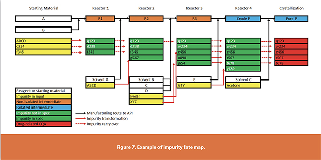
Because the impurity concentration in the final product is highly important, an impurity fate map should be developed from the steady-state models. The impurity fate map tracks the concentration of important compounds in the process, including unreacted reagents, products and intermediates, impurities generated at each stage, impurities entering the process with inlet materials, catalysts, solvents, and any other components that would be treated as critical impurities in the final product.17 The impurity fate map is one of the most important documents for quality control, QbD, and regulatory communications (Figure 7). The accuracy of the model results and stream compositions should be validated by analytical chemistry testing, such as High-Performance Liquid Chromatography (HPLC).
The dynamic simulation should focus on the process at a state of control (not the start-up and shut-down time) and evaluate disturbance scenarios during the steady manufacturing time. Dynamic modeling outcomes include risk analysis, control strategies, mitigation plans, alarm setpoints, and volume and location of surge vessels and deviation valves.18
PAT is one of the main components of a CM line. Batch systems mainly rely on offline tests and analytical chemistry for quality control. In CM processes, on-line or in-line PAT tools are synced with the SCADA system to monitor the process performance and alert the operator of any deviation from the state of control.19
The combination of mechanistic models, PAT tools, and SCADA systems makes a true Digital Twin with diverse applications from advanced process control to predictive maintenance and condition based monitoring to operators training (Figure 8).19 Active control tools maintain process control and allow continuous release of product downstream, or, by a real-time release testing (RTRT) paradigm, allow the release of the final product to collection vessels.
Further Reading and Extension of the Discussion
This short article cannot cover all the aspects of the process design for a CM line. There are several remaining important features that can be discussed in future works. Some of them are: the PAT tools, end-to-end CM versus hybrid system, surge vessels and buffer tanks sizing, RTD study, types of disturbances and control strategies, GMP considerations and regulatory approaches, data management, control system design, process validation, flexible manufacturing, and start- up and shutdown, and technoeconomical analysis.
References
- Nagy, Z.K., A.E. Hagrasy, and J. Litster, Continuous Pharmaceutical Processing. 2020: Springer International Publishing.
- Yazdanpanah, N., Continuous Manufacturing in the Pharmaceutical Industry. CEP, 2021. 117(3): p. 28-35.
- Teoh, S.K., C. Rathi, and P. Sharratt, Practical Assessment Methodology for Converting Fine Chemicals Processes from Batch to Continuous. Organic Process Research & Development, 2016. 20(2): p. 414-431.
- McWilliams, J.C., et al., The Evolving State of Continuous Processing in Pharmaceutical API Manufacturing: A Survey of Pharmaceutical Companies and Contract Manufacturing Organizations. Organic Process Research & Development, 2018. 22(9): p. 1143-1166.
- Cole, K.P., et al., Kilogram-scale prexasertib monolactate monohydrate synthesis under continuous-flow CGMP conditions. Science, 2017. 356(6343): p. 1144-1150.
- Laporte, T.L., C. Wang, and S. Jones, Process Development and Case Studies of Continuous Reactor Systems for Production of API and Pharmaceutical Intermediates, in Chemical Engineering in the Pharmaceutical Industry, D.J.a. Ende, Editor. 2011, John Wiley & Sons, Inc. p. 319-339.
- Berton, M., et al., Scaling continuous API synthesis from milligram to kilogram: extending the enabling benefits of micro to the plant. Journal of Flow Chemistry, 2020. 10(1): p. 73- 92.
- Ende, D.J.a. and M.T.a. Ende, Chemical Engineering in the Pharmaceutical Industry. 2019: John Wiley & Sons, Inc.
- Yazdanpanah, N. Pharmaceutical Process Intensification Via Continuous Manufacturing and the Role of Modeling and Simulation. in 2019 AIChE Annual Meeting. 2019. AIChE.
- Yazdanpanah, N., C.N. Cruz, and T.F. O’Connor, Multiscale modeling of a tubular reactor for flow chemistry and continuous manufacturing. Computers & Chemical Engineering, 2019. 129: p. 106510.
- Yazdanpanah, N. and Z.K. Nagy, The Handbook of Continuous Crystallization. 2020: Royal Society of Chemistry.
- Yazdanpanah, N., T. O’connor, and C. Cruz, Dynamic Modeling of a Continuous Reactive Crystallization Process, in AIChE Annual Meeting 2018. 2018, AIChE: Pittsburgh, PA, USA.
- Marchisio, D.L., et al., Role of turbulent shear rate distribution in aggregation and breakage processes. AIChE Journal, 2006. 52(1): p. 158-173.
- Hu, C., et al., Development of an automated multi-stage continuous reactive crystallization system with in-line PATs for high viscosity process. Reaction Chemistry & Engineering, 2018. 3(5): p. 658-667.
- Minnich, C.B., et al., Determination of the Dispersion Characteristics of Miniaturized Coiled Reactors with Fiber-Optic Fourier Transform Mid-infrared Spectroscopy. Industrial & Engineering Chemistry Research, 2010. 49(12): p. 5530-5535.
- Lepore, J., T. Mahmood, and R. Hartman, Development of a Quality Risk Based Tool for the Selection of Regulatory Starting Materials for Commercial Drug Substance Manufacturing Processes. Organic Process Research & Development, 2020. 24(11): p. 2762-2771.
- Li, Y., et al., Analytical control of process impurities in Pazopanib hydrochloride by impurity fate mapping. Journal of Pharmaceutical and Biomedical Analysis, 2010. 52(4): p. 493-507.
- Yazdanpanah, N., T. O’connor, and C. Cruz, Process Modeling of a Continuous Drug Substance Manufacturing Process, in AIChE Annual Meeting 2018. 2018, AIChE: Pittsburgh, PA, USA.
- Ganesh, S., et al., Design of condition-based maintenance framework for process operations management in pharmaceutical continuous manufacturing. International Journal of Pharmaceutics, 2020. 587: p. 119621.
Author Biography
Nima Yazdanpanah, PhD, is a consultant on advanced manufacturing and modeling and simulation in the bio/ pharmaceutical and fine chemical industries. His area of expertise covers mathematical modeling, process simulation, particulate matters, process design, and advanced manufacturing. Prior to starting his consultancy firm, Procegence, he was a research scientist with the U.S. Food and Drug Administration (FDA). He was appointed as a member of an expert team to advance emerging technologies and modernize pharmaceutical manufacturing. Yazdanpanah was a postdoctoral research associate at the Massachusetts Institute of Technology (MIT) and Novartis-MIT Center for Continuous Manufacturing. He earned his PhD in chemical engineering from the Univ. of Sydney. He has worked for years in petrochemical, food, and pharmaceutical industry for R&D and process design sections.