Single-use systems (SUS) promise many benefits to the biopharmaceutical industry including reduced cross-contamination risks, lower capital investment, elimination of cleaning and sterilization operations, reduced turnaround times, and the ability to scale an operation up or down with limited additional investment [1,2]. SUS are provided in a sterile, readyto- use format, or as non-sterile parts for user processing.
Despite the potential benefits, SUS are sometimes not chosen because of real and perceived obstacles to implementation. System integrity, particulate contamination, and extractables are leading areas of concern that must be addressed by suppliers and end users [3-7]. Although these concerns are familiar in biopharmaceutical manufacturing, they are made more worrisome by the perceived loss of control when converting to single-use technologies. SUS suppliers become operational partners. Core activities such as equipment qualification, cleaning validation, sterilization validation, and sterile assembly manufacture are not handled by the SUS user. Equipment availability, formerly controllable though maintenance and engineering efforts, becomes dependent upon supply chain reliability. Process equipment configuration control transitions to a supplier change management activity [2].
How to be Successful with Single-Use Technology
Success with SUS requires a team effort from procurement, planning, supply chain management, logistics, operations, process engineering, quality, and component engineering departments. Recognize that the SUS supplier is an essential part of the team and incorporate them at appropriate times [2, 3, 8]. All team members must understand and address the concerns that limit implementation, and they should be prepared to not deploy single-use technology when it does not make sense for the business.
It is helpful to dedicate engineering staff (component engineering) to assume responsibilities throughout the lifecycle of design, deployment, support, and disposal of SUS. Manufacturing facilities that rely on SUS are continually refreshed with new parts. The team that specifies the parts needs to respond to changing demand, identified design weaknesses, and supplier changes. The best designed assembly will be of no help if it is not available to meet the production schedule. Component engineers need to stay engaged in supply chain management activities to ensure success with SUS.
While recognizing the many other critical roles in SUS supply chain management, the remainder of this article emphasizes component engineering tasks.
Good Engineering Practices for Design and Deployment of Single-Use Technologies
Component engineers collaborate with process engineering and operations groups to match SUS options with process design, ergonomics, and facility requirements. Component engineers design and manage parts that will operate reliably and support robust supply chain performance. Simplification and standardization are key objectives.
Good engineering practices and standards are the foundation for engineering work. Single-use technology engineering standards describe SUS that can be supported by engineering and supply chain management. Standard SUS should be validated to meet the anticipated range of process requirements. Engineering standards also provide design principles and qualification methods to address those rare situations where new parts are required. Effective internal standards will influence and align with industry standards. Standards become evident when good engineering practices yield business success.
User Requirements
Those who are new to SUS frequently jump to the design, or even the purchasing stage without a proper understanding of process requirements. Do not start by making drawings of assemblies, looking at existing parts, or leafing through supplier literature. Know what your assembly must do before you start designing it. A formalized process for generating a user requirements specification (URS) will support fast and accurate SUS deployment.
URS preparation starts with a process description supplied by the product manufacturing area expert. The chemical composition, temperature, and pressure at each point in the process must be known before proceeding to detailed design and parts selection. An annotated block flow diagram showing where material enters and exits the process, and listing critical process parameters, will suffice to guide discussions about the process details required to define the assembly subparts.
Time invested in URS preparation benefits the component engineer, supplier, and end user. Process details lead to proper choices of materials of construction and component sizes. The details also assist in the establishment of a component qualification program that supports the intended process use.
In a high-performing organization, many of the requirements will be standardized. For example, information about the following attributes is necessary to make design selections and fulfill quality expectations:
- Biocompatibility
- Mechanical properties
- Gas/Vapor transmission
- Compendial physicochemical properties
- TSE-BSE status
- TOC analysis
- pH/conductivity of rinsate
- Extractables and leachables
- Chemical compatibility
- Protein adsorption studies
- Endotoxin testing
- Sterilization validation
- Container Closure Integrity (CCI)
- Particulates (USP <788>, EP 2.9.19, visible)
- Calibration of embedded instrumentation
These attributes, how they are measured, and related regulations and standards are described in the literature [1,9,10]. There is no need to discuss these requirements during each SUS design project. A standard URS approach will allow focus on the novel aspects of the process.
Specifications and Knowledge Management
The next step is to match the URS with the engineering standards. Rather than custom designing parts to meet the needs of productspecific project teams, the component engineer should equip the organization with a catalog of items that will meet the needs of most biopharmaceutical processes. Component engineering programs should strive to do very little new design.
Build and maintain a collection of parts and assemblies that may be used in a product independent fashion. Adding similar parts to the collection should be avoided as each additional part contributes to supply chain and inventory management complexity. Support costs rise with the number of parts, and operational flexibility decreases when unique parts are specified for each product or process.
Engineers need a library of specifications for the qualified SUS collection. The library should contain controlled information such as drawings, validation guides, and internally generated testing and validation data. The library should also hold technology and supplier-specific references.
If the library does not contain an adequate match to the URS, then external sourcing of new parts is required. The URS will be combined with business requirements before contacting suppliers. Procurement and supply chain management should participate in all URS development. However, their level of involvement and leadership increases in external sourcing projects.
Building the SUS Collection
Components: The simplest form of single-use technology
Components are items such as silicone tubing, polypropylene connectors, and capsule filters. These are examples of single-use items that have been accepted in biopharmaceutical manufacturing for years [2]. Despite familiarity with these purchased items, users may not fully understand the parts or know why particular parts were selected. Design guidance is needed to help with replacements, upgrades, or extensions to other processes.
The internal standard for components should define:
- Preferred materials of construction (MOC): A selection guide will help match MOC with process parameters.
- Dimensions: Tubing lengths and diameters should be limited.
- Junctions: Choices are made from a restricted set of validated tubing/fitting/fastener combinations.
It is advisable to qualify “off the shelf” catalog components for the standard collection.
Assemblies: Groupings of components
Components are linked together to form fluid transport assemblies. Before starting design, the need for connections should be challenged. Does the fluid have to be moved or can the process be conducted in a single container? Is it possible to move the container rather than transferring fluid?
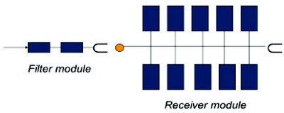 Figure 1. Schematic of a simple modular process to fi lter liquid into a set of containers. Generic connectors are represented by the “U” and orange dot. Closed system connectors or tube welding could be used to make these connections downstream of the fi lters. The system can be extended using the connection point on the right, or this point can be sealed to terminate the chain.
There are four common options for combining components into a complete processing system:
- The traditional approach: Purchase components and make connections. Steam-sterilize the assemblies.
- The lean-thinking and process optimization approach: Purchase multi-component assemblies, connect as needed, and sterilize.
- The reasonable approach for single-product facilities: Purchase process-specifi c assemblies that are irradiated and ready to use.
- The “modular” approach to provide operational flexibility and reduce support costs: Purchase ready-to-use subassemblies and connect as needed with closed system connectors. Figure 1 illustrates an “expand to fi t” modular approach for a liquid fi ltration operation.
The internal standard for assemblies should define:
- Decision-making methodology for “make vs. buy” decisions
- Design principles for making connections and building assemblies
- Specifi cations for qualifi ed subassemblies (modules)
- A selection guide to match module connectors with process requirements
- Approved disconnection methods and supplies Standard connections/disconnections need to cover a design space that spans the majority of anticipated applications.
The following heuristics are off ered to start discussion about best practices in SUS design. Best practices will vary with organization size, number of products and product types supported, and local regulatory requirements.
 Figure 2. Increasing junction complexity decreases the number of mechanical connections in fluid transport networks. The left side of this fi gure shows two networks, one with 4 inlet/outlets and one with 5. Using 4-way junctions leads to the simplifi ed designs on the right. They have the same number of inlet/outlets, but fewer potential leak points.
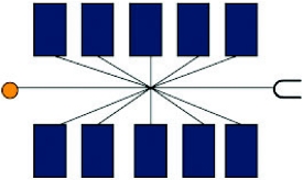 Figure 3. Schematic of a high complexity flow splitter and flexible tubing module that can replace the module shown on the right side of Figure 1.
- Minimize material types in each assembly and in the collection to reduce engineering support, validation, and change management efforts.
- Select junctions to meet requirements, and minimize the number of junctions. Minimizing the number of junctions must be weighed against increases in module size. One way to reduce connections inside modules is to use the highest possible degree of flow splitting (furcation) in a single molded component. As shown in Figure 2, the number of connections or molded junctions is reduced by using 4-way rather than 3-way connection points. The principle applies for higher order connectivity. As single piece connectivity increases, the chance of leaks decreases.
- Separate “furcation” from “translation”: Take advantage of flexible single-use tubing and split fluid paths in one location. Imitating “hard piped” systems as shown in Figure 1 makes assembly more complicated and provides more points of failure. A high degree of connectivity that might be enabled by flexible tubing and a high complexity molded flow splitter is illustrated in Figure 3. Note that “simple and standard” may look different than “hard piped” or customdesigned single-use systems.
- Balance complexity across modules: Avoid creating assemblies that are difficult to build and handle by distributing parts among modules. The less complicated assemblies should include the tubing needed to transport fluids to adjacent, more complicated, assemblies. It is a good idea to break up modules into those with a transformative function (filters, for example) and those with only fluid transport functions. The transport modules should contain the majority of the tubing required for the fully assembled, end-to-end process.
- Employ a “design once – use many” strategy for modular design to simplify management of SUS. Most of the work done to engineer and qualify modules will not need to be repeated for each new process application.
- Test “first article” shipments from suppliers for all new designs. This goes beyond evaluation of a “prototype” in that it evaluates all aspects of the SUS that will be in the routine supply chain. The whole package – pallets, cartons, packing materials, documentation, labels, and the parts themselves – is the SUS, and the whole thing needs to work for all stakeholders. First articles should be handled by suppliers and end users as planned for normal production. Monitor packaging, paperwork, and the single-use item itself as the first article goes through packaging, shipment and receipt, unpacking, stocking in clean warehouse space, delivery to end user facilities, movement to point of use, use, and disposal.
Change Management
Changes may be requested by the end user, recommended by the supplier, or imposed on both parties by changes made by resin suppliers, regulators, or other difficult-to-control sources. Technical, quality, regulatory, and business decisions need to be made whenever changes happen. It is a good idea to predetermine how changes of various types will be handled.
A well-constructed component and assembly library will limit the number of internal changes. Users are advised to develop supply and quality agreements that limit the number of supplier-initiated changes. Rules for how to manage changes will facilitate continuous improvement activity both internally and from the SUS manufacturers when necessary. Users need to negotiate with suppliers to ensure that existing product lines continue to be manufactured and supported even as innovative technologies are launched. The automotive, pharmaceutical, and software industries provide examples of old designs coexisting with new designs.
Summary
The benefits of SUS can be realized by developing and implementing good engineering practices and standards. Devise a detailed strategy that works for your manufacturing and supply chain management capabilities. Users are advised to:
- Start with a user-requirements specification.
- Design to meet requirements.
- Source standard supplier products where possible.
- Define and enforce internal best practices and standards for components and assemblies.
- Adopt a modular design approach: “Design once – use many”.
- Recognize suppliers as supply chain partners.
- Limit internal changes and work with suppliers to maintain existing product lines.
References
- Eibl, R. and Eibl, D. eds. “Single-Use Technology in Biopharmaceutical Manufacture”, John Wiley & Sons. Inc., Hoboken, New Jersey, 2011.
- Vogel, J.D. “The Maturation of Single-Use Applications”, BioProcess International 10(S5), 2012, 10-19.
- Craig, J.L. and Jenkins, M., “Toward Flexible Hybrid Facilities of the Future”, BioProcess Int. 10(11) s 2012:34-37
- Langille, S.E., “Particulate Matter in Injectable Drug Products”, PDA J Pharm Sci and Tech 2013, 67 186-200.
- Riedman, D. and Martin, J., “A Case Study in Qualification of Single-Use Filling Manifolds for Particles and Endotoxins”, BioProcess Int. 9(S2) 2011: 28-35.
- Mahajan, E., Ray-Chaudhuri, T., and Vogel, J.D., “Standardization of Single-Use Components’ Extractable Studies for Industry” Pharmaceutical Engineering 32(3) 2012: 54-56.
- Jenke, D. Evaluation of the chemical compatibility of plastic contact materials and pharmaceutical products; safety considerations related to extractables and leachables. J. Pharm. Sci. 2007, 96 (10), 2566 –2581.
- Jenness, E. and Gupta, V. “Implementing a Single-Use Solution for Fill-Finish Manufacturing Operations”, BioProcess Int. 9(S2) 2011: 22-26.
- BPSA Guidelines and Standards Committee, “Part 1, Bio-Process Systems Alliance Component Quality Test Matrices”, BioProcess Int. 5 (4) 2007: 52-67 Document also available at www.bpsalliance.org/guides.html
- BPSA Guidelines and Standards Committee, “Bio-Process Systems Alliance Component Quality Test Matrices; Part Two: Tubing and Filters”, BioProcess Int. 5(4S) 2007: 16-23. Document also available at www.bpsalliance.org/guides.html
Author Biography
Dr. Mark A. Petrich is Associate Director at Merck & Co. and serves on the Bio-Process Systems Alliance (BPSA) board of directors. His work emphasizes single-use technologies in vaccine and biologics manufacturing. Mark holds both his BS and Ph.D. in Chemical Engineering.