Bristol-Myers Squibb (BMS) presents a one-of-a-kind isolator system as a spectacular addition to an award winning facility. The BMS Clinical Supplies Manufacturing and Drug Product Technology Center was the ISPE 2008 Facility of the Year Award winner in equipment innovation. BMS has continued that world class innovation with the implementation of a potent compound capable isolated syringe filler.
This qualified filling system is used to process clinical scale investigational product. Clinical scale manufacturing poses numerous challenges to standard equipment design and common practices for process handling. The design of this system was brought to life with exceptional effort and persistent ingenuity.
Syringe Filling
“The objective of aseptic processing is to produce a sterile product and to minimize or eliminate potential sources of contamination in the product [1].” Syringe Filling is a type of aseptic processing that fill syringes directly instead of filling vials and transferring drug to syringes just prior to patient delivery. Vial filling has been the conventional method for the aseptic fill of parenteral products. Syringe filling is quickly becoming a preferable method of drug delivery. Pre-filled syringes, minimize if not eliminate, the necessity for wasteful overfill. The United States Pharmacopeia recommends as little as 2% overfill in pre-filled syringes as compared to conventional drug delivery systems that can require up to 25% [2]. The decreased overage required in syringes vs. conventional systems can result in an increased number of doses available to patients as well as a reduction of manufacturing costs potential contamination. However, the greatest benefit is for patients as this simplifies administration and is more convenient. In addition, recent advancements in syringe technology have expanded the possibilities for the future of pre-filled syringes and provided a number of new options for drug delivery systems such as the dual chamber syringe with separate lyophilizedcake and diluent sections and injection system designs based on the patient’s specific needs.
Isolation
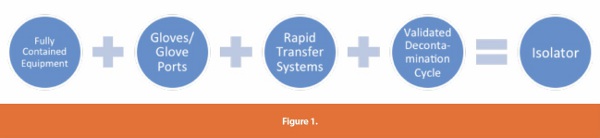
ISPE defines an isolator as “a decontaminated unit, Grade 5 conditions, that provides uncompromised, continuous, isolation of its interior from the surrounding environment” [3]. The isolation equation includes the following:
BMS chose isolation primarily because of the multiple benefits to the operation and level of sterility assurance to the product. Isolators eliminate reliance on manual processes, such as formal room decontamination and operator gowning to cover all skin exposure, and instead rely largely on engineering controls. The reduced gowning requirement increases operator comfort and eliminates the periodic aseptic gowning qualification. Isolators eliminate the product’s exposure to the external environment and employee contact with the product.
When considering isolator technology, there are several design factors to take into account to install fully contained equipment. Facilities have process area and equipment space constraints. In addition, facilities need sufficient real estate for adequate material flows. When all these factors have been taken into account, the isolators/filling equipment need to be decontaminated and hence the process and equipment have to be adjusted to accommodate the chemical treatment. Therefore, it is critical for the end user to work closely with the equipment vendors and facility engineering staff at the start of a project to minimize unexpected obstacles. Adjustments to the process equipment are significantly more difficult, costly and time consuming to modify when the equipment is out of the vendor’s hands and at the user site.
Isolator design requires forethought to accommodate a range of employee characteristics that funnel into glove port height, positions and glove size. For this reason, glove manipulations and movements within the isolator must be well understood during the design phase. Operators need to adapt to isolator environments and processes. Imagine putting on the thickest winter gloves and carrying out your daily activities. It’s not so easy to button up a shirt or open a can of soda with thick gloves on.
There is an increased focus on preparation when considering how to introduce products/components into the isolator and how to remove filled product from the isolator, without breaking the sterile barrier. As a result, all items brought into an isolator are typically steam sterilized and transferred in to the isolator via circular Rapid Transfer Port systems. All the factors that funnel into creating the clean isolated environment is formalized by the validated decontamination cycle, which is detailed below.
VHP Decontamination Cycle
Decontamination requires the use of a chemical to sanitize the inside surfaces of the isolator chambers. This system requires microbial qualification. Any equipment or process supplies necessary for production can enter the isolator in one of two ways. Items can be steam sterilized and transferred into the isolator after the decontamination cycle is complete. If an item can’t be steam sterilized, it must be must be hung in the isolator prior to decontamination and must withstand the chemical sanitization treatment.
The VHP cycle is considered a decontamination process - a way to kill microorganisms in the environment and reduce the population of organisms on surfaces by a target amount. The cycle utilizes hydrogen peroxide at 35% concentration in the liquid form. The liquid is dropped onto a heated plate at a controlled rate to vaporize it. The vapor form allows the hydrogen peroxide to be carried throughout the open spaces within the isolator. Since it is known that microorganisms die in a logarithmic curve, there are mathematical models that adequately indicate the behavior of the cycle. The performance is defi ned by the log reduction of an organisms population based on the time it takes to achieve a one log reduction in the specifi c isolator system. This is known as the D-value of a given organism in that isolator.
The D-value is obtained within a given isolator by exposing a set of Biological Indicators to VHP for a varied amount of time. Biological Indicators are strips containing a known population of an organism, usually greater than 1x10^6 organisms. The data obtained during cycles of varied exposure are utilized to determine the D-value for a specifi c isolator.
This D-value is then utilized in calculating and projecting the cycle length necessary to obtain a given log reduction for the production cycle. The main advantage of the isolated fi lling line is to allow for a qualifi ed cycle to reproducibly decontaminate surfaces and ensure decontamination (6 log reduction) or a stronger sterility assurance level with a 12 log or greater reduction. To illustrate the signifi cance of a 12 log reduction, let’s take the human hand as an example.
There are typically between 10,000 and 10 million bacteria on each hand [4]. Assuming the human hand has 1 million bacteria on it, a decontamination process with a 12 log reduction applied to that hand would result in a 1 in 1 million chance of a single organism remaining on that hand after the decontamination process. It must also be kept in mind that although a longer cycle will provide a greater level of sterility assurance, it also can extend the required time necessary to remove all of the hydrogen peroxide from the chamber prior to the start of the fi ll.
VHP is a contact decontaminant. It can only reliably decontaminate a surface if it has access to that surface. This can then become challenging in an isolator where there are moving filling parts that are at times occluded and for items that need to be placed on the floor of the isolator. For example there are moving parts associated with the tub manipulation robot, stoppering mechanism and conveyors.
Tub Introduction
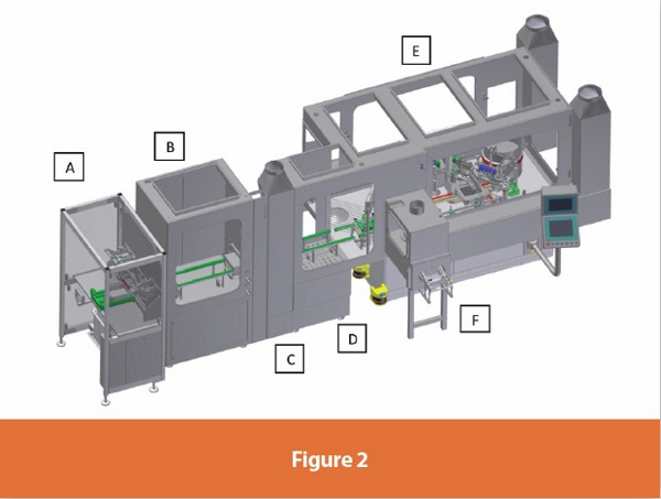
When choosing isolator technology for syringe filling, it is vital to consider the method of tub introduction. A standard syringe tub consists of 100 or 160 nested syringes in a plastic tub with a liner and a seal. The tub is a rectangular object, approximately 10”x9”x4” in size, and physically not able to fi t through a standard sized circular Rapid Transfer Port. Extensive consideration needs to be taken in order to maintain the sterility of the isolator and the tub during the aseptic transfer. The aseptic transfer can be completed in various ways. The tub can be passed into the isolator manually or via an automated, decontamination batch process. If choosing a decontamination process, the type of product fi lling should guide the appropriate choice of tub decontamination. The tub can also be manually decontaminated or sanitized once inside the isolator as well. However, any added stages of tub introduction can result in undesirable excess handling. Treating the tub, either manually or automatically, with decontamination or sanitizing agents could result in varied levels of penetration of the chemical and potential product reactive chemical residue in the syringes. Ultimately, there is less risk of procedurally introducing organisms with less manual handling. The operation described in Figure 2 combine an automated entry process with additional space for an optional manual decontamination step.
Process Flow
This state of the art system is designed as a batch operating process. The process begins with double bagged gamma-irradiated syringe tubs delivered on carts to the manufacturing area. The syringe tubs contain fully nested syringes in 10”x10” or 10”x16” confi gurations. The double bagged syringe tub containers are cleaned with a disinfectant and placed on process area dedicated carts. The clean process area carts are moved next to the debagger. The outer bag of the double bagged syringe tubs is removed and the single bagged syringe tubs are placed on a disinfected stainless steel table.
A dedicated person operates the debagger. The debagger (A) is the syringe tub entry way into the isolated system. It consists of a table, mechanical knife, pusher bar and small vacuum system with overhead laminar flow for low-particulate unidirectional flow air. It allows for a repeatable process that minimizes operator handling. A dedicated person picks up a single bagged syringe tub and places it on the debagger table. The debagger holds the tub in place while removing the bag with a covered, rolling mechanical knife. The operator can use the bag and the pusher bar to transfer the tub into the isolator “airlock” (B) without any manual manipulation of the syringe tub interior.
The debagger and the isolator airlock are connected by a syringe tub sized “mousehole”. The tub moves along a dedicated rail system into the isolator airlock. In the isolator airlock, the operator can load several syringe tubs on wall mounted shelves awaiting the filling process. The airlock area is a positively pressurized space that can be used to store or decontaminate the tub prior to staging the syringe tub for filling. When prompted, an operator manually (through isolator gloves) transfers a syringe tub from the isolator airlock into the syringe filling isolator along a dedicated rail system. The airlock is connected to the syringe filler by a small isolator chamber called a positive-negative-positive (PnP) gate (C). The PnP gate maintains the desired pressure cascade for the syringe filling isolator and contains a lower pressure than both the airlock and the filling isolator, to serve as a pressure.
Inside the syringe filler isolator (D), there is a small area dedicated to removing the protective cover of the syringe tub. The protective cover and liner sheet are removed and placed into a dedicated RTP disposal can located directly across from the operator location. The syringe tub is then manually (through isolator gloves) passed to the isolated syringe filling staging area (E). This staging area is protected by glove light barriers and a stainless steel gate. These barriers protect both the personnel and the robotic operation of the syringe filling arm. Once the syringe tub is positioned, the filler robotic arm removes the nest of syringes from the tub and positions it in a nesting guide. The nest guide will hold the syringes during filling and stoppering. The arm then moves the tub to the exit area of the filler. The nest guide moves under the filling needles and stoppering mechanism via X/Y coordinates to fill and stopper all syringes. Once completed, the full syringe nest is transferred back into the empty tub already placed at the exit area.
The tub exits the isolator via an automated conveyor belt system into the (F) exit gate. The PnP exit gate is an isolator chamber that completes the pressure cascade system for the potent capable isolator. A lid is placed on the filled, nested syringes once they exit the isolated system. They are transferred to a clean cart where they await further downstream processing.
Potent Technology
The isolator system described above is made up of several individual chambers. These chambers provide the pressure cascades necessary to allow this isolated system to be potent compound process capable. The specific addition of the negatively pressured exit chamber protects the operator’s environment while maintaining the positively pressured filling isolator. To increase confidence for potent material movement, this system completely eliminated vacuum driven mechanical movements were completely eliminated from the system.
To compliment this setup the machine also has a ‘toxic product’ mode, for greater operator control over automated tub movement processes. The addition of the exit chamber guarantees greater flexibility for manufacturing options during drug development. For example, experimental data can be lacking at early stages of the drug development process. Since the facility processes material for R&D purposes only, the products range from pre-clinical to late Phase 2 and sometimes early Phase 3 Clinical Trial products. The exit chamber allows for the production of a wider range of products at any stage with minimal change to the syringe filling process.
Added Flexibility
A large majority of the batches made are handled at a “larger than lab bench” scale for the first time and hence the liquid flow properties are often unknown for clinical scale batches. For this reason, the filler capability required a flexible in-process weight check program. Products that have historical fi ll weight data will require less frequent weight checks than a new product with minimal historical data. Weight check frequency can also be aff ected by batch size. Batch size can vary from a small quantity for early clinical trials up tobatches ten times as large for later stage trials. Another factor is the time it takes to perform the weight checks, as performing numerous checks reduces efficiency and hence throughput. The filling system was programmed to accommodate these varying batch attributes. Product specific weight check options are built in for varying the pattern of syringes to check within the tub. This accommodates viscosity and other flow properties of the liquids filled.
The filler has the option of using dual rotary piston pumps or peristaltic pumps, which results in fill volumes between 0.1mL and 10mL. This includes liquids with varying flow characteristics and highly viscous materials. The machine has the capability of processing syringes from 1mL up to 50mL syringe barrel sizes and of purging the syringe headspace with nitrogen for oxygen sensitive products.
The machine was also designed to utilize a completely disposable product pathway. This feature eliminates cross contamination concerns related to the changeover from one product to the next and also eliminates the time and cost of developing cleaning verification analytical tests. The design of this program was a collaborative effort between the vendor and BMS, and demonstrates the execution of a challenging concept- planning for unknown processes.
Conclusion
This uniquely designed system continuously evolved at every stage of the equipment design. The process flexibility demanded by clinical scale manufacturing continually tested customary equipment design practices. The ultimate result is a superior system that can process sterile liquids of varying flow characteristics, a wide range of fill volumes and container sizes and highly potent/toxic and/or radioactive substances, while maintaining an aseptic filling environment. With this addition of a first-in-class clinical scale isolated, potent compound capable syringe filler, BMS is poised to accelerate drug development and delivery.
References
1. ISPE Baseline Guide Second Edition, September 2011, pg. 16
2. Lane, Brian and Rhines, Timothy PhD, ‘Ensure Quality, Safety of Prefilled Syringes’ http://www.pharmaquality. com/ME2/Audiences/dirmod.asp?nm=Browse+Articles& type=Publishing&mod=Publications%3A%3AArticle&mid=D3E3C719D8D44216836DCA4F4144BEC4&tier=4&id=DEE72FDB29DD4F72837432CC023ECEF2&AudD=564 8A5C28C97462DBBDB309539B820EF)
3. ISPE Baseline Guide Second Edition, September 2011, pg. 134
4. Health Protection Agency, Fun Facts Publication, http:// www.hpa.org.uk
Author Biographies
Caroline Eichberger currently works as a Process Engineer in the Clinical Supply Operations department at BMS. She has extensive experience in the field of Parenteral manufacturing, including the manufacture of lyophilized and liquid filled vials, pre-filled syringes, and IV bags. Caroline has also served as the project lead on the process scale up of products in development, as well as several complex equipment and facility projects, including the addition of a biologics suite to a small molecule manufacturing facility and the qualification of different types of isolated Parenteral filling machines. Caroline holds a Bachelor of Science in Biological Engineering from Cornell University.
Laurie Mastellone is currently employed as an Outsourcing Specialist for Clinical Supply Operations at Bristol-Myers Squibb. She has a range of experience in the drug development process, including both biologic and pharmaceutical manufacture of vials and pre-filled syringes. She has extensive knowledge in process equipment design for parenteral formulation, filling operations and isolator integration. Laurie holds a Bachelor of Science in Chemical Engineering from Drexel University and a Masters of Business Administration from New York University Stern School of Business.