Dr. Mauro Giusti - Senior Director Site External Network
Eli Lilly Italia – President, PDA Italy Chapter
Abstract
Now more than ever companies manufacturing parenteral products with aseptic filling are urged to look at barrier technologies, either Restricted Access Barrier Systems (RABS) or isolators. This article describes the experience of a company using two types of isolators for aseptic filling of cartridges and syringes and provides some practical recommendations regarding design, qualifications, start-up, and routine operations.
The recent COVID-19 pandemic has brought more attention to the pharmaceutical industry as vaccines and monoclonal antibodies have been developed to help fight the pandemic. Vaccines and monoclonal antibodies are parenteral products filled in vials or syringes and produced through aseptic filling without terminal sterilization. Manufacturing these products is complex because of the challenges of aseptic filling. The traditional aseptic filling, considering the concepts outlined in the draft New Annex 1, is not well accepted for new lines, and instead there is a strong push toward implementation of barrier technologies, which in essence means either RABS or isolators.
This article will focus on isolator technology, providing some suggestions from 20 years of experience using isolators for aseptic filling (and for sterility testing), with a continuous growth in terms of volume, markets, products, and equipment.
Figure 1 summarizes Lilly Italia’s experience with isolator technology
- A first-generation sterility testing isolator with peracetic acid mixture and flexible walls
- Three modern sterility testing isolators based on VPHP
- Two high speed cartridges lines, equipped with three isolators each (the filling isolator, the material transfer chamber, the connection panel)
- One high-speed syringe line, equipped with two isolators (the filling isolator, the material transfer chamber)
Also, the figure highlights that the Lilly Italia plant has a RABS line in place, dedicated to flexible production; RABS technology has some commonalities and some key differences versus isolator technology . However, the use of a RABS line within the same plant is important to be able to compare the two technologies, as well as to retain specific aseptic capabilities which are very important in clean room operations.
Isolator Technology Benefits
Considering the many years of implementation, we can summarize that isolation technology, for the proper process, with proper equipment and know how, can results in many benefits:
• Sterility testing
- » Reduction of likelihood of sterility failures
- » Reduction of likelihood of EM hits
- » Training of personnel much easier
- » Cost of utilities, gowning, etc. much lower
• Aseptic filling
- » Reduction of likelihood of sterility failures or APS failures
- » Reduction of likelihood of EM hits
- » Elimination of class A hits, with subsequent no need to reject product if root cause not understood » Reduced chances of human errors due to higher level of automation
- » Increase of productivity due to:
- Less time employed for people to gown and degown
- Ability to run long campaign with multiple lots
- » Training of personnel much easier
- » Cost of utilities, gowning, etc. much lower versus the standard aseptic cleanroom
In the two specific cases we are dealing with, cartridges and syringes, set up of the filling lines are a little different.
Description of the Filling Lines and Their Isolator System
- Syringe line is using prewashed, pre-siliconized, presterilized staked-in needle glass syringes placed in tubs inserted in a double gas permeable bag (Ethylene Oxide sterilization). The plungers are prewashed, pre-siliconized and gamma sterilized, placed into a RTP (Rapid Transfer Port) plastic bag attached to isolator. Filling is accomplished with 10 peristaltic pumps placed inside isolator, pushing liquid from a surge tank fed by tubing with an external point of use filtration system. Connections are performed directly in the isolator. A material transfer chamber is used to decontaminate on the outside materials sterile inside (e.g., EM supplies). Please refer to Figure 2 illustrating a schematic description of the line.
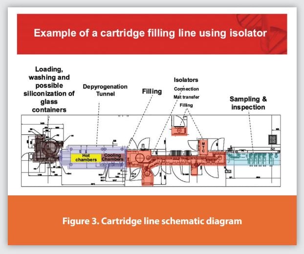
- Cartridge line is used for washing, siliconizing, depyrogenating, polymerizing, and cooling the glass cartridges. Then steam sterilized glass beads, plungers and disc seals are used. Glass beads (which are only used for insulin suspension products) are washed and siliconized in component processing systems then inserted in an autoclavable bags and steam sterilized in autoclave. Plungers are coming from suppliers prewashed and pre-siliconized, then steam sterilized on site in component processing systems. Disc seals are washed and steam sterilized in component processing systems on site. Filling is accomplished with a time pressure filling system equipped with a first shot filling 24 cartridges at a time and a second shot time pressure laser sensor system which is filling 12 units at a time. All 36 needles are taking liquid from the same manifold, whose pressure is controlled to remain constant. Please refer to figure 3 illustrating a schematic description of the line.

The isolator for cartridges has a specific VPHP vaporizing unit and each isolator is managed by a dedicated HVAC system. Cycle starts with heating and dehumidifying the chamber, then VPHP is vaporized passing through HEPA filters until a constant level of VPHP ppm is achieved, then maintained at a given level for a given duration, then the aeration cycle starts until the ppm level is below a given value.
The isolator for syringe line is different because of two aspects, use of process compressed air to push the VPHP instead of a real HVAC system, then the VPHP is vaporized bypassing the HEPA filters, and finally the aeration is supported also by a catalytic converter.
Both types of isolators (the largest chamber, approximately 20 cubic meters) can perform the entire cycle in about five hours, which is a small percentage of the overall time that is required between the end of a campaign and the start of the next.
Recommendations
From 2005 to 2020 we have started and run three large isolators for filling operations, and we have developed some experience and some learnings, which are reported here below:
Design
• Provide project team with adequate capabilities and perform benchmarking
• Verify product compatibility with VPHP, suitability of technology for line portfolio
• Define isolation technology: robust HVAC design, VPHP through or bypass HEPA filters, closed or open loop, VPHP elimination/ reduction technology
• Select the right vendor - one that has knowledge of isolator cycle/VPHP generation, integration with filler, possibility to perform tests during FAT, possibility to perform mockup, possibility to assist during cycle development and start-up
• Define details - construction material suitable for VPHP, material and process flow during operations, EM sampling points and technology integration of EM system and filling, interventions including maintenance ones, Quality by Design in the automation logic
Qualifications
• Commissioning and Qualification (C&Q) - Define the upfront C&Q approach (e.g., ISO2500), ensure site people's participation to C&Q, decide extent of FAT tests versus tests on site. Place special focus on the automation part, as sometimes software bugs may be discovered too late
• Cycle - Repeat on-site cycle development with facility qualified and in operation status, special focus on the qualification of decontamination for sterile materials to be introduced, special focus on cleaning /sanitization of RTP doors
• Process Qualification (PQ) - make sure to perform line integrated PQ at the end of individual PQs and prior to APS to verify:
- Integration of isolator with tunnel (if present) or component entry (tubs), with filler and with glove testing
- Environmental Monitoring (EM) operations (viable + total particles)
- Impact of facility/operations (i.e., Delta P and temperature fluctuation)
• VPHP Cycle - develop strong technical knowledge and reasonable criteria for initial and periodic validation of the cycle and good know-how and qualification of BIs.
Aseptic Process Simulation
• Define upfront Aseptic Process Simulation (APS) strategy: to get started, end in mind to match planned output, defi ne upfront allowed interventions
• Design APS: starting from formulation, defining a hybrid which is matching all possible combinations of products/containers worst case, bundling interventions and filling APS after each bundle, avoid to fill excessive number of units
• Prepare people with training including aseptic practices (isolator does require aseptic practices)
• Perform detailed PFMEA to defi ne upfront what to do in case of issues: broken gloves, loss of overpressure, leaks, etc.
Routine Operations
• Define type of support required (Engineering, Maintenance, QA, Sterility Assurance, Technical Services), both if on shift and on day. Defi ne capabilities required for each function
• Define process monitoring parameters and periodic reviews of data and actions: for example, broken gloves, EM viable and Total Particles, alarms, cycles, pressure fluctuation events, leaks
• Define program to include unplanned interventions in APS program, criteria to break isolator sterility in case of issues, Have clear “end in mind” for campaign definition
• Ensure a reliable supply of BI with low variability
Specific Issues Working with Isolators
There are seven main categories of issues, which sometimes can be combined (for example an equipment breakdown could cause loss of decontaminated status and EM hit):
1. Failure during cycle annual revalidation – Figure 4
2. Loss of decontaminated status due to pressure fluctuations – Figure 5
3. Microbiological EM hits – Figure 6
4. Total particles spike out of limits in the isolator – Figure 7
5. Glove/flexible door breakage – Figure 8
6. Anomalous trend of VPHP cycle – Figure 9
7. Major equipment breakdown – Figure 10
Figures 4 through 10 are suggesting how to approach and investigate those situations, listing possible root causes and valuating possible impact.
Conclusions
Isolator technology properly designed and managed ensures better sterility assurance and quality standardization (e.g., ensuring less dependence from people). For sterility testing it is becoming the standard equipment.
However, as with all equipment and processes, it is subject to issues. The ability to understand how to first prevent and then best manage those issues makes the difference between success and failure. The cross-functional integration of competent and motivated people ensures the minimization and the best management of the issues.
Subscribe to our e-Newsletters
Stay up to date with the latest news, articles, and events. Plus, get special
offers from American Pharmaceutical Review delivered to your inbox!
Sign up now!