Introduction
In a Good Manufacturing Practice (GMP) environment, the goal of cleaning is to remove the product and cleaning agent residues (if a cleaning agent other than water is used) to an acceptable level. Various methods of cleaning process equipment are utilized, such as clean-in-place (CIP), clean-out-of-place (COP), and manual cleaning, to achieve this goal. GMP facilities widely use CIP systems to clean process equipment such as vessels, inner surfaces of transfer pipes, and various fittings without the need to have the time-consuming tasks of disassembly and reassembly of the parts. The other advantage of a CIP system is its consistency and repeatability in the cleaning process, which uses automated washing, rinsing, and drying sequences.
The objective of this article is to provide a good understanding of the effect of the properties of the fluids and flow dynamics on the effectiveness of the CIP cleaning process in the transfer pipes.
Clean in Place Process
Pharmaceutical process equipment design includes minimizing dead legs; pipes sloped towards the drain for drainability, use of sanitary fittings, etc., and are often taken into consideration. A useful reference for sanitary and cleanability design requirements is the ‘P3 A Standards for Pharmaceutical Manufacturing.’1 Another reference related to biopharmaceutical manufacturing is the ‘American Society of Mechanical Engineers Bioprocessing Equipment (ASME-BPE) standard.’2 When designing and sizing a CIP system, sufficient flow and pressure in the process pipes and spray ball are required to effectively remove the soil to an acceptable level in an efficient and timely manner.
The effectiveness of cleaning in CIP systems depends on various factors such as the following:
- Spray ball configuration and coverage. Coverage of the cleaning agent in the vessel is critical, as no contact with the cleaning agent means no cleaning takes place.
- Type and the number of fittings used. Sanitary fittings such as diaphragm valves are preferred, as these have good cleanability design.
- Appropriate installation of instrumentation or probes with minimal dead-leg space.
- Materials of construction and surface finish. Smoother surface finishes have better or easier cleanability.
- Drainability of system and drying effectiveness.
- Fluid flow dynamics of cleaning solution in the transfer lines (pipes). Fluid dynamics are related to the various fluid flow parameters which can influence the fluid flow conditions in the pipes, and in turn, impact the cleaning efficiency. An example is minimum flow velocity to achieve turbulent flow and to prevent air entrapment at 90° bends.
The use of CIP systems is common in the cleaning of vessels, transfer lines, and other process equipment that may also utilize spray devices such as spray balls. A CIP system is normally designed to clean the transfer pipes as well as the vessels, which can involve the flow of cleaning solution and water through the network of pipes.
Fluid flow plays a vital role in the cleaning of closed processes. It affects the efficiency of the cleaning process as the type of fluid flow is closely linked with the cleaning action and is dependent on the motion of the cleaning solution (i.e., the motion of detergent and/ or water). Turbulent flow is preferred over laminar flow during the cleaning process in pipes, as the turbulent flow has a flatter velocity profile across the cross-section of the pipe (Figure 3), which can facilitate the removal of soils on the surfaces. Cleaning is a process in which the soils are removed from the surface by breaking the forces between the soil and the surfaces using an appropriate cleaning agent, cleaning time, temperature, and mechanical shear stress.
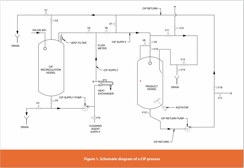
Figure 1 shows a simplified version of a CIP process for a vessel. In general, the CIP skid has a recirculation tank that supplies the CIP cleaning solution (can be a solution of water or formulated detergent) via a CIP supply pump to the target vessel via the piping network. The cleaning solution is typically sprayed onto the inner surface of vessels using spray balls to provide coverage, and to some extent, impingement action on the surface depending on the types of spray devices.
For the Clean-in-Place process, CIP boundaries or circuits need to be defined. CIP circuits usually involve vessels with some parts of connecting or transfer pipes. Depending on the design of the CIP process, connecting or transferring pipes may have separate CIP cleaning circuits. All these CIP cleaning circuits (or boundaries) have various pipe fittings and even branches in the circuits. It is useful to understand the cleaning sequence and also the flow dynamics and the concepts involved in designing a CIP system. Understanding the characteristics of fluid flow in these transfer pipes enables the optimal design of the CIP system to facilitate efficient cleaning.
Fluid Flow: Fundamental Concepts
There are many different categories of fluid flows, depending on the conditions. The following are some examples of different flow categories (Saleh, M.J., 2002):
- Laminar or turbulent flow
- Newtonian or non-Newtonian flow
- Compressible or incompressible flow
- Homogeneous or heterogeneous (two-phase) flow
- Isothermal or non-isothermal flow
- Steady or unsteady state flow
A fluid flow may involve different combinations of the above flow conditions. The different flow categories require different solution assumptions and generate different results. For CIP systems, the washing and rinsing solutions are mainly cleaning solutions and water. The assumption is that these are considered turbulent, Newtonian, incompressible, homogeneous, isothermal, and steady-state fluid flow conditions in the closed system. The following are brief descriptions of the characteristics of the flow conditions in most well-designed CIP systems (Saleh, M.J., 2002).
- Turbulent flow is preferred for the cleaning process, as this is more effective in the removal of soil from the surfaces.
- A constant viscosity characterizes Newtonian fluids at constant temperature and pressure. The viscosity of a Newtonian fluid is equal to the shear stress divided by the rate of deformation.
- Incompressible flow has negligible density change. Velocity is the same, and the kinetic term may be dropped unless there is a decrease or increase in the cross-sectional flow area.
- Homogeneous flow applies when the soil is completely dissolved in the cleaning solution and is purely a uniform liquid (water, cleaning agent, and dissolved soil) flow. If the soil is not completely dissolved in the cleaning solution, the soil suspended in the cleaning solution affects the fluid properties and flow dynamics.
- Isothermal flow conditions in a CIP system display no drastic change in the temperature of the fluids and hence will not drastically affect the fluid properties and flow dynamics. For a CIP system in which the temperature cannot be controlled, the temperature of the fluid drops during the recirculation of the cleaning solution. In this case, this is not considered an isothermal flow, and the change in temperature needs to be assessed for the impact on the fluid properties and flow dynamics.
- Steady-state flow condition, in which the hydrodynamic properties such as velocity, Reynolds number, and pressure drop are constants and independent of time, except at start-up or shut-down, or when there are adverse events such as pump or power failure.
Significance of Laminar Versus Turbulent Flow and Reynolds Number in Cleaning Applications
In order to comprehend the fluid flow dynamics from the cleaning perspective, it is important to understand the characteristics and differences of laminar and turbulent flows and the meaning of the dimensionless Reynolds number. The significance of each of these from a cleaning application perspective is discussed in detail.
Laminar Flow
Laminar flow occurs at a lower flow velocity. In laminar flow, the resistive forces between adjacent layers are dominant. This resistive force is the greatest at the wall, where it may reduce the velocity to zero at the pipe wall. Laminar flow is characterized by uniform, smooth, undisturbed, and unmixed parallel layers of the fluid. When the fluid flow velocity is low, the velocity profile of fluid flow follows the parabolic curve (Refer to Figure 2). The highest velocity is at the center of the pipe. As the distance to the surface of pipes decreases, the velocity of the fluid also decreases.
At the steady-state, average fluid velocity for laminar flow is obtained by dividing the volumetric flow rate in the pipe by the pipe’s cross-sectional area, as shown in equation (1) (Saleh, M.J., 2002):
Laminar flow velocity equations are shown below (Saleh, M.J., 2002):
From equation (2), at the center of the pipe where r = 0, the velocity is maximum, and it is twice the average velocity. At the wall of the pipe where r = R, the velocity is reduced to 0.
From a cleaning perspective, laminar flow in CIP systems may not be desired as there can be a thin layer of static fluid at the wall. Since the laminar flow velocity profile is parabolic, there is a rapid drop in flow velocity from the center of the pipe, and also the flow is smooth and in parallel layers throughout the cross-sectional area. These characteristics may not facilitate the removal of soil from the surfaces. Instead, these conditions may allow microbial residues to develop biofilm conditions.
Turbulent Flow
Turbulent flow occurs when the layers are moving in a random direction with random mixing between layers. At higher velocities, the viscous forces in the fluid are unable to dampen out random fluctuations in the fluid motion, and there is macromixing (mixing of fluid from adjacent layers) among the fluid layers. Macromixing is due to the small, high-frequency velocity fluctuations superimposed on the mean motion of a turbulent flow. One of the characteristics is the rapid movement of eddies in the fluid stream. Eddies are small fluid elements that have a rapid swirling motion and can move quickly in different directions. It is the presence of these eddies that causes the mixing of the different layers of fluid flow. More energy is dissipated in turbulent flow than in laminar flow due to the increased motion of eddies, which accounts for the pressure drop observed in these scenarios.
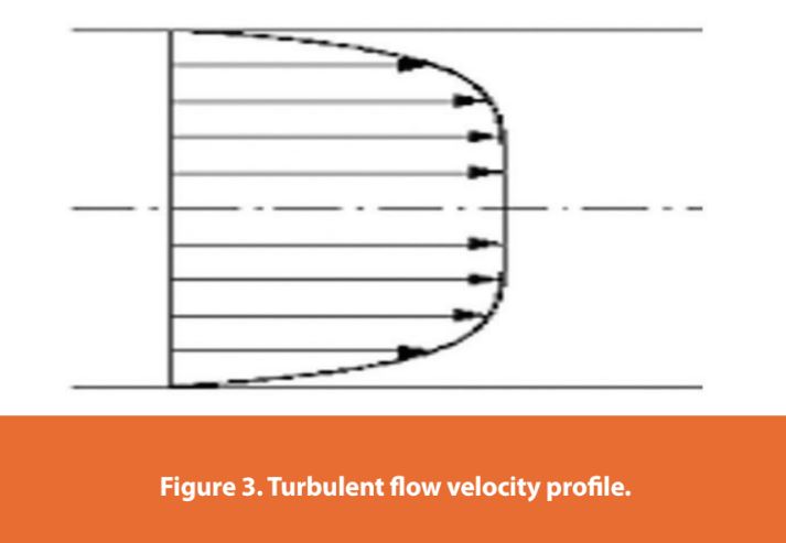
The velocity profile for turbulent flow is much flatter as it increases rapidly to the average velocity. The velocity in turbulent flow at any radial position may be estimated by Prandtl’s 1/7th power law, as shown in (3) below (Saleh, M.J., 2002):
Equation (4) is applicable at high Reynolds numbers, where the laminar sub-layer is very small. This equation can be expressed as a function of the average velocity using equation (4) (Saleh, M.J., 2002).
The velocity gradient at the pipe wall is much more significant for turbulent flow (refer to Figure 3), and this change in velocity profile leads to a sharp increase in the wall shear stress, with the same effect on the friction factor. In turbulent flow, the zone immediately beside the wall surface is known as a viscous sublayer. The wall surface dampens the cross-stream mixing and turbulent fluctuations, and as a result, this very thin viscous sublayer is essentially laminar.
Although turbulent flow has a very thin laminar viscous sublayer near the pipe wall surface, it has a flatter velocity profile compared to laminar flow and is recommended in CIP cleaning processes as there is more movement of small masses of fluid elements across the pipe flow cross-sectional area, which may facilitate the removal of soil or other contaminants.
Reynolds Number
The Reynolds number can determine the type of flow (laminar or turbulent flow) in a pipe. It is a dimensionless number that characterizes the ratio of inertia and viscous forces. A low Reynolds number is obtained when viscous forces (viscosity) are much larger than inertia forces, which are characterized by laminar flow. Conversely, a high Reynolds number is obtained when inertia forces predominate when there is high velocity or low viscosity. A high Reynolds number causes turbulent flow. The same concepts can be applied to tank flow, whether the liquid flowing/cascading on the side wall of a tank is laminar or turbulent, although the equations and criteria are different.
The following is the formula for determining the Reynolds number for cylindrical pipes or tubes with full flow (Saleh, M.J., 2002):
Where
Re Reynolds number
G Mass flow rate, kg/s
µ Fluid dynamic viscosity, kg•m−1•s−1
D Pipe Diameter, m
V Fluid velocity, m/s
ρ Fluid density, kg/m3 F
Example,
For cleaning a 2-inch pipe at 25°C using water, the Reynolds number can be calculated as follows:
ρ = 997 kg m-3
µ = 0.0091 poise (kg•m−1•s−1)
D = 0.0508 m
V = 1.5 m s-1
In this example, the dimensionless Reynolds number of 8,349 with a flow velocity of 1.5 m/s is obtained. This number indicates the presence of turbulent flow in the 2-inch pipe.
The Reynolds number in a pipe can be changed easily by varying the flow velocity. As the flow velocity increases, the Reynolds number increases, and there is a transition into turbulent flow. It also depends on numerous factors related to fluid properties such as fluid viscosity and density, and the dimension of the flow element, such as the diameter of the pipe. For flow in pipes with full flow, the transition from laminar flow into turbulent flow occurs at approximately 2100 < Re < 2300 (Saleh, M.J., 2002).
Applications of Flow Dynamics in CIP Systems
CIP system design and configurations are generally known since these are required to meet user requirements in the cleaning process. As mentioned earlier, turbulent flow in pipes is desired during the CIP cleaning process, which means a minimum Reynold’s number of 4,000. In addition, air removal from the piping system is also essential, especially at the pipe bends or dead legs area. Studies show that a minimum velocity of 1.5 m/s (5 ft/s) is required for air removal (Verghese, G., et al, 2009). Some configurations of dead legs may require even higher velocity. Air removal from the system during cleaning is critical as bubbles of air can prevent the cleaning solution from contacting the surface.
It can be seen here that the Reynolds number alone is not the determining factor in the design of the CIP system. It also depends on the pipe diameter, flow velocity, and configurations, including the type of fixture. As an example, if the Reynolds number is 5,000 for turbulent flow in a 2-inch pipe, the velocity based on equation (5) is 0.9 m/s. This velocity is below the recommended velocity for effective air removal from bends, dead legs, etc. The Reynolds number needs to be increased to 10,000 for the flow velocity to be 1.8 m/s (above 1.5 m/s). Table 1 shows an illustration of the values for the Reynolds numbers, flow velocity, and flow rates relating to various pipe diameters.
Conclusion
Understanding the concept of flow dynamics in a closed process is beneficial to anyone associated with CIP systems. It also shows how the Reynolds number is related to the type of fluid flow in a closed system (whether laminar or turbulent flow). Fluid flow dynamics play an essential role in the CIP process. They can influence the CIP cleaning process by ensuring turbulent flow conditions in pipes during cleaning and can certainly make the cleaning process more robust, efficient, and effective in the removal of soil.
References
- P3-A Standards for Pharmaceutical Manufacturing. 3-A Sanitary Standards, Inc., McLean, Va.
- The American Society of Mechanical Engineers, ASME BPE-2022, Bioprocessing Equipment.
- Jamal M. Saleh. Fluid Flow Handbook. McGraw-Hill Handbooks (2002). (Page 1.2, 5.1, 5.2, 5.4, 5.6, 5.8, 5.9, 18.7, 18.10)
- Verghese, G. and Lopolito, P. Chapter 8 - Cleaning Engineering and Equipment Design (Page 137). Cleaning and Cleaning Validation, Volume 1. Co-published by PDA and DHI (2009).
Author Details
Richard Chai- STERIS Corporation
Publication Details
This article appeared in American Pharmaceutical Review: Vol. 27, No. 5July/Aug 2024Pages: 70-74
Subscribe to our e-newsletters.
Stay up to date with the latest news, articles, and events. Plus, get special
offers from American Pharmaceutical Review delivered to your inbox!
Sign up now!